PIC12F510/16F506
TABLE 10-2: CAPACITOR SELECTION FOR
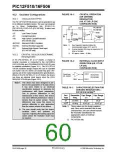
CRYSTAL OSCILLATOR –
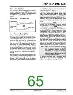
FIGURE 10-3:
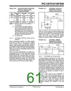
EXTERNAL PARALLEL
RESONANT CRYSTAL
OSCILLATOR CIRCUIT
PIC12F510/16F506(2)
+5V
Osc.
Type
Resonator Cap.Range Cap. Range
To Other
Devices
Freq.
C1
C2
10k
32 kHz(1)
15 pF
15 pF
4.7k
74AS04
LP
XT
200 kHz
1 MHz
4 MHz
47-68 pF
15 pF
15 pF
47-68 pF
15 pF
15 pF
CLKIN
74AS04
PIC12F510
PIC16F506
(3)
10k
HS
20 MHz
15-47 pF
15-47 pF
XTAL
Note 1: For VDD > 4.5V, C1 = C2 ≈ 30 pF is
recommended.
10k
2: These values are for design guidance
only. Rs may be required to avoid over-
driving crystals beyond the drive level
specification. Since each crystal has its
own characteristics, the user should con-
sult the crystal manufacturer for appropri-
ate values of external components.
20 pF
20 pF
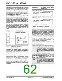
Figure 10-4 shows a series resonant oscillator circuit.
This circuit is also designed to use the fundamental
frequency of the crystal. The inverter performs a 180-
degree phase shift in a series resonant oscillator
circuit. The 330 Ω resistors provide the negative
feedback to bias the inverters in their linear region.
3: PIC16F506 only.
10.2.3
EXTERNAL CRYSTAL OSCILLATOR
CIRCUIT
FIGURE 10-4:
EXTERNAL SERIES
RESONANT CRYSTAL
OSCILLATOR CIRCUIT
Either a prepackaged oscillator or a simple oscillator
circuit with TTL gates can be used as an external
crystal oscillator circuit. Prepackaged oscillators
provide a wide operating range and better stability. A
well-designed crystal oscillator will provide good perfor-
mance with TTL gates. Two types of crystal oscillator
circuits can be used: one with parallel resonance or one
with series resonance.
To Other
Devices
330
330
74AS04
74AS04
74AS04
CLKIN
0.1 mF
XTAL
PIC12F510
PIC16F506
Figure 10-3 shows implementation of a parallel reso-
nant oscillator circuit. The circuit is designed to use the
fundamental frequency of the crystal. The 74AS04
inverter performs the 180-degree phase shift that a
parallel oscillator requires. The 4.7 kΩ resistor provides
the negative feedback for stability. The 10 kΩ potenti-
ometers bias the 74AS04 in the linear region. This
circuit could be used for external oscillator designs.
10.2.4
EXTERNAL RC OSCILLATOR
For timing insensitive applications, the EXTRC device
option offers additional cost savings. The EXTRC oscil-
lator frequency is a function of the supply voltage, the
resistor (REXT) and capacitor (CEXT) values, and the
operating temperature. In addition to this, the oscillator
frequency will vary from unit-to-unit due to normal pro-
cess parameter variation. Furthermore, the difference
in lead frame capacitance between package types will
also affect the oscillation frequency, especially for low
CEXT values. The user also needs to take into account
variation due to tolerance of external R and C
components used.
Figure 10-5 shows how the R/C combination is
connected to the PIC12F510/16F506 devices. For
REXT values below 5.0 kΩ, the oscillator operation may
become unstable or stop completely. For very high
REXT values (e.g., 1 MΩ), the oscillator becomes
sensitive to noise, humidity and leakage. Thus, we
recommend keeping REXT between 5.0 kΩ and
100 kΩ.
© 2006 Microchip Technology Inc.
Preliminary
DS41268B-page 59

 ETC [ ETC ]