PIC12F510/16F506
FIGURE 10-1:
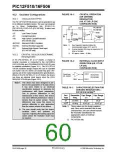
CRYSTAL OPERATION
(OR CERAMIC
RESONATOR)
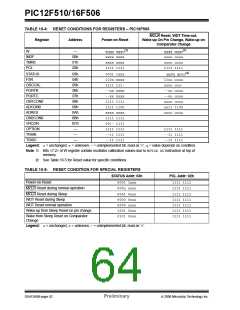
10.2 Oscillator Configurations
10.2.1
OSCILLATOR TYPES
(HS, XT OR LP OSC
CONFIGURATION)
The PIC12F510/16F506 devices can be operated in up
to six different oscillator modes. The user can program
up to three Configuration bits (FOSC<1:0>
[PIC12F510], FOSC<2:0> [PIC16F506]). To select one
of these modes:
(1)
C1
PIC12F510
PIC16F506
OSC1
OSC2
Sleep
•LP:
•XT:
•HS:
Low-Power Crystal
Crystal/Resonator
XTAL
(3)
RF
To internal
logic
High-Speed Crystal/Resonator
(PIC16F506 only)
(2)
RS
(1)
C2
•INTOSC: Internal 4/8 MHz Oscillator
•EXTRC: External Resistor/Capacitor
Note 1: See Capacitor Selection tables for
recommended values of C1 and C2.
2: A series resistor (RS) may be required for AT
strip cut crystals.
•EC:
External High-Speed Clock Input
(PIC16F506 only)
3: RF approx. value = 10 MΩ.
10.2.2
CRYSTAL OSCILLATOR/CERAMIC
RESONATORS
In HS (PIC16F506), XT or LP modes, a crystal or
ceramic resonator is connected to the (GP5/RB5)/
OSC1/(CLKIN) and (GP4/RB4)/OSC2/(CLKOUT) pins
to establish oscillation (Figure 10-1). The PIC12F510/
16F506 oscillator designs require the use of a parallel
cut crystal. Use of a series cut crystal may give a fre-
quency out of the crystal manufacturers specifications.
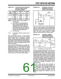
When in HS (PIC16F506), XT or LP modes, the device
can have an external clock source drive the (GP5/
RB5)/OSC1/CLKIN pin (Figure 10-2).
FIGURE 10-2:
EXTERNAL CLOCK INPUT
OPERATION (HS, XT OR
LP OSC
CONFIGURATION)
OSC1
Clock from
ext. system
PIC12F510
PIC16F506
Open
OSC2
Note 1: This device has been designed to per-
form to the parameters of its data sheet.
It has been tested to an electrical
specification designed to determine its
conformance with these parameters.
Due to process differences in the
manufacture of this device, this device
may have different performance charac-
teristics than its earlier version. These
differences may cause this device to
perform differently in your application
than the earlier version of this device.
TABLE 10-1: CAPACITOR SELECTION FOR
CERAMIC RESONATORS –
PIC12F510/16F506(1)
Osc.
Type
Resonator Cap. Range Cap. Range
Freq.
C1
C2
XT
HS(2)
4.0 MHz
16 MHz
30 pF
30 pF
10-47 pF
10-47 pF
Note 1: These values are for design guidance
only. Since each resonator has its own
characteristics, the user should consult
the resonator manufacturer for
appropriate values of external
2: The user should verify that the device
oscillator starts and performs as
expected. Adjusting the loading capacitor
values and/or the Oscillator mode may
be required.
components.
2: PIC16F506 only.
DS41268B-page 58
Preliminary
© 2006 Microchip Technology Inc.

 ETC [ ETC ]