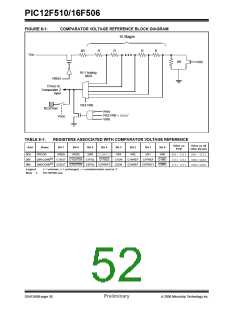
PIC12F510/16F506
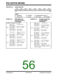
REGISTER 9-2:
ADRES REGISTER
R-X R-X
R-X
R-X
R-X
R-X
R-X
R-X
ADRES7 ADRES6 ADRES5 ADRES4
bit 7
ADRES3 ADRES2 ADRES1 ADRES0
bit 0
Legend:
R = Readable bit
-n = Value at POR
W = Writable bit
‘1’ = Bit is set
U = Unimplemented bit, read as ‘0’
‘0’ = Bit is cleared
x = Bit is unknown
EXAMPLE 9-1:
PERFORMING AN
ANALOG-TO-DIGITAL
CONVERSION
EXAMPLE 9-2:
CHANNEL SELECTION
CHANGE DURING
CONVERSION
MOVLW 0xF1
MOVWF ADCON0
;configure A/D
;Sample code operates out of BANK0
MOVLW 0xF1
;configure A/D
BSF ADCON0, 1 ;start conversion
BSF ADCON0, 2 ;setup for read of
;channel 1
BTFSC ADCON0, 1;wait for ‘DONE’
GOTO loop0
MOVWF ADCON0
BSF ADCON0, 1 ;start conversion
BTFSC ADCON0, 1;wait for ‘DONE’
GOTO loop0
MOVF ADRES, W ;read result
MOVWF result0 ;save result
loop0
loop1
loop2
loop0
MOVF ADRES, W ;read result
MOVWF result0 ;save result
BSF ADCON0, 2 ;setup for read of
;channel 1
BSF ADCON0, 1 ;start conversion
BTFSC ADCON0, 1;wait for ‘DONE’
GOTO loop1
BSF ADCON0, 1 ;start conversion
BSF ADCON0, 3 ;setup for read of
BCF ADCON0, 2 ;channel 2
BTFSC ADCON0, 1;wait for ‘DONE’
GOTO loop1
loop1
loop2
MOVF ADRES, W ;read result
MOVWF result1 ;save result
MOVF ADRES, W ;read result
MOVWF result1 ;save result
BSF ADCON0, 3 ;setup for read of
BCF ADCON0, 2 ;channel 2
BSF ADCON0, 1 ;start conversion
BTFSC ADCON0, 1;wait for ‘DONE’
GOTO loop2
BSF ADCON0, 1 ;start conversion
BTFSC ADCON0, 1;wait for ‘DONE’
GOTO loop2
MOVF ADRES, W ;read result
MOVWF result2 ;save result
CLRF ADCON0
;pins to Digital mode and turns off
;the ADC module
MOVF ADRES, W ;read result
MOVWF result2 ;save result
;optional: returns
DS41268B-page 54
Preliminary
© 2006 Microchip Technology Inc.

 ETC [ ETC ]