PIC12F510/16F506
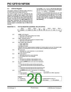
REGISTER 4-2:
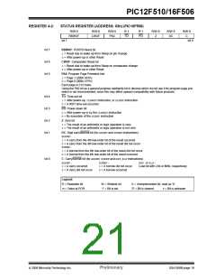
STATUS REGISTER (ADDRESS: 03h) (PIC16F506)
R/W-0
R/W-0
CWUF
R/W-0
PA0
R-1
TO
R-1
PD
R/W-X
Z
R/W-X
DC
R/W-X
C
RBWUF
bit 7
bit 0
bit 7
bit 6
bit 5
RBWUF: PORTB Reset bit
1= Reset due to wake-up from Sleep on pin change
0= After power-up or other Reset
CWUF: Comparator Reset bit
1= Reset due to wake-up from Sleep on comparator change
0= After power-up or other Reset
PA0: Program Page Preselect bits
1= Page 1 (200h-3FFh)
0= Page 0 (000h-1FFh)
Each page is 512 bytes.
Using the PA0 bit as a general purpose read/write bit in devices which do not use it for program page pre-
select is not recommended, since this may affect upward compatibility with future products.
bit 4
bit 3
bit 2
bit 1
TO: Time-out bit
1= After power-up, CLRWDTinstruction, or SLEEPinstruction
0= A WDT time-out occurred
PD: Power-down bit
1= After power-up or by the CLRWDTinstruction
0= By execution of the SLEEPinstruction
Z: Zero bit
1= The result of an arithmetic or logic operation is zero
0= The result of an arithmetic or logic operation is not zero
DC: Digit carry/borrow bit (for ADDWFand SUBWFinstructions)
ADDWF:
1= A carry from the 4th low-order bit of the result occurred
0= A carry from the 4th low-order bit of the result did not occur
SUBWF:
1= A borrow from the 4th low-order bit of the result did not occur
0= A borrow from the 4th low-order bit of the result occurred
bit 0
C: Carry/borrow bit (for ADDWF, SUBWFand RRF, RLFinstructions)
ADDWF:
SUBWF:
RRF or RLF:
1= A carry occurred
0= A carry did not occur
1= A borrow did not occur
0= A borrow occurred
Load bit with LSb or MSb, respectively
Legend:
R = Readable bit
-n = Value at POR
W = Writable bit
‘1’ = Bit is set
U = Unimplemented bit, read as ‘0’
‘0’ = Bit is cleared
x = Bit is unknown
© 2006 Microchip Technology Inc.
Preliminary
DS41268B-page 19

 ETC [ ETC ]