PIC12F510/16F506
4.6.1
EFFECTS OF RESET
4.6
Program Counter
The PC is set upon a Reset, which means that the PC
addresses the last location in the last page (i.e., the
oscillator calibration instruction). After executing
MOVLW XX, the PC will roll over to location 00h and
begin executing user code.
As a program instruction is executed, the Program
Counter (PC) will contain the address of the next
program instruction to be executed. The PC value is
increased by one every instruction cycle, unless an
instruction changes the PC.
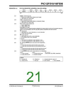
The STATUS register page preselect bits are cleared
upon a Reset, which means that page 0 is preselected.
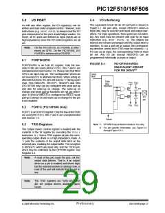
For a GOTOinstruction, bits 8:0 of the PC are provided
by the GOTO instruction word. The Program Counter
(PCL) is mapped to PC<7:0>. Bit 5 of the STATUS
register provides page information to bit 9 of the PC
(Figure 4-4).
Therefore, upon a Reset, a GOTO instruction will
automatically cause the program to jump to page 0 until
the value of the page bits is altered.
For a CALL instruction, or any instruction where the
PCL is the destination, bits 7:0 of the PC again are
provided by the instruction word. However, PC<8>
does not come from the instruction word, but is always
cleared (Figure 4-4).
4.7
Stack
The PIC12F510/16F506 devices have a 2-deep, 12-bit
wide hardware PUSH/POP stack.
A CALLinstruction will PUSH the current value of Stack
1 into Stack 2 and then PUSH the current PC value,
incremented by one, into Stack Level 1. If more than
two sequential CALLs are executed, only the most
recent two return addresses are stored.
Instructions where the PCL is the destination or modify
PCL instructions include MOVWF PC, ADDWF PCand
BSF PC, 5.
Note:
Because PC<8> is cleared in the CALL
instruction or any modify PCL instruction,
all subroutine calls or computed jumps are
limited to the first 256 locations of any
program memory page (512 words long).
A RETLW instruction will POP the contents of Stack
Level 1 into the PC and then copy Stack Level 2
contents into Stack Level 1. If more than two sequential
RETLWs are executed, the stack will be filled with the
address previously stored in Stack Level 2.
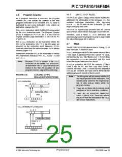
FIGURE 4-4:
LOADING OF PC
Note 1: The W register will be loaded with the lit-
eral value specified in the instruction. This
is particularly useful for the implementa-
tion of data look-up tables within the
program memory.
BRANCH INSTRUCTIONS
GOTOInstruction
9 8 7
0
PC
PCL
2: There are no Status bits to indicate stack
overflows or stack underflow conditions.
Instruction Word
3: There are no instruction mnemonics
called PUSH or POP. These are actions
that occur from the execution of the CALL
and RETLWinstructions.
PA0
0
7
STATUS
CALLor Modify PCL Instruction
9 8 7
0
PC
PCL
Instruction Word
Reset to ‘0’
PA0
7
0
STATUS
© 2006 Microchip Technology Inc.
Preliminary
DS41268B-page 23

 ETC [ ETC ]