Freescale Semiconductor, Inc.
Designer Reference Manual — 3-ph. ACIM Drive with DTC
Section 5. System Setup
5.1 Contents
5.2
5.3
5.4
5.5
5.6
5.7
5.8
Hardware Setup . . . . . . . . . . . . . . . . . . . . . . . . . . . . . . . . . . . .49
Warning . . . . . . . . . . . . . . . . . . . . . . . . . . . . . . . . . . . . . . . . . .50
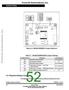
Jumper Settings of Controller Board. . . . . . . . . . . . . . . . . . . . .51
Required Software Tools . . . . . . . . . . . . . . . . . . . . . . . . . . . . .52
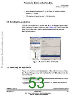
Building the Application . . . . . . . . . . . . . . . . . . . . . . . . . . . . . .53
Executing the Application . . . . . . . . . . . . . . . . . . . . . . . . . . . . .53
Controlling the Application with PC Master Software . . . . . . . .57
5.2 Hardware Setup
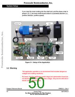
Figure 5-1 illustrates the hardware setup of the application. It
incorporates the following modules:
• MC68HC908MR32 Control Board
• 3-phase AC/BLDC High Voltage Power Stage
• Optoisolation Board
• 3-phase AC Induction Motor
The correct phase order (phase A, phase B, phase C) for the shown AC
induction motor is:
• Phase A — red wire
• Phase B — white wire
• Phase C — black wire
DRM019 — Rev 0
MOTOROLA
Designer Reference Manual
System Setup
49
For More Information On This Product,
Go to: www.freescale.com

 ETC [ ETC ]