Freescale Semiconductor, Inc.
System Description
Dead Time Distortion Correction
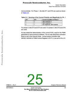
microcontroller. For Phase 1, the bits DT1 and DT2 are used as shown
in Table 2-3.
Table 2-3. Sensing of the Current Polarity and Magnitude for Ph. 1
DT1
DT2
Current Condition of Phase 1
high magnitude I+
high magnitude I-
0
1
0
0
1
1
low magnitude, either polarity
For phase 2, bits DT3 and DT4 are used. For phase 3, bits DT5 and DT6
are used.
As was stated the determination of the correct PVAL used for the PWM
generation is done purely by software. The on-chip dead time correction
block is set in the manual mode - current sense correction bits
ISENS1:ISENS0 of PWM Control Register 0 (PCTL1) are set to 00 or 01.
DRM019 — Rev 0
MOTOROLA
Designer Reference Manual
System Description
25
For More Information On This Product,
Go to: www.freescale.com

 ETC [ ETC ]