HY29F800
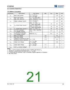
DC CHARACTERISTICS
TTL/NMOS Compatible
Parameter
Description
Test Setup
Min
Typ
Max
±1.0
Unit
µA
VIN = VSS to VCC,
CC = VCC Max
ILI
Input Load Current
V
Input Load Current
A[9], OE#, RESET#
VCC = VCC Max; A[9] =
OE# = RESET# = 12.5 V
VOUT = VSS to VCC,
ILIT
ILO
35
±1.0
40
µA
µA
Output Leakage Current
VCC = VCC Max
CE# = VIL, OE# = VIH,
f = 5MHz, Byte Mode
CE# = VIL, OE# = VIH,
f = 5MHz, Word Mode
19
mA
ICC1
VCC Active Read Current 1, 2
19
36
50
60
mA
mA
mA
ICC2
ICC3
VCC Active Write Current 2, 3, 4 CE# = VIL, OE# = VIH
VCC CE# Controlled
TTL Standby Current 2
OE# = CE# = RESET#
= VIH
0.4
1.0
VCC RESET# Controlled
TTL Standby Current 2
ICC4
RESET# = VIL
0.4
1.0
mA
VIL
VIH
Input Low Voltage
Input High Voltage
-0.5
2.0
0.8
VCC + 0.5
V
V
Voltage for Electronic ID and
Temporary Sector Unprotect
VID
VOL
VOH
V
CC = 5.0V
11.5
12.5
0.45
V
V
VCC = VCC Min,
Output Low Voltage
I
OL = 5.8 mA
VCC = VCC Min,
Output High Voltage
2.4
3.2
V
V
I
OH = -2.5 mA
VLKO
Low VCC Lockout Voltage4
4.2
Notes:
1. The ICC current is listed is typically less than 2 mA/MHz with OE# at VIH.
2. Maximum ICC specifications are tested with VCC = VCC Max.
3. ICC active while the Automatic Erase or Automatic Program algorithm is in progress.
4. Not 100% tested.
Rev. 4.0/Jan. 00
21

 ETC [ ETC ]