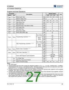
HY29F800
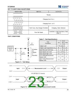
KEY TO SWITCHING WAVEFORMS
WAVEFORM
INPUTS
OUTPUTS
Steady
Changing from H to L
Changing from L to H
Don't Care, Any Change Permitted
Does Not Apply
Changing, State Unknown
Centerline is High Impedance State
(High Z)
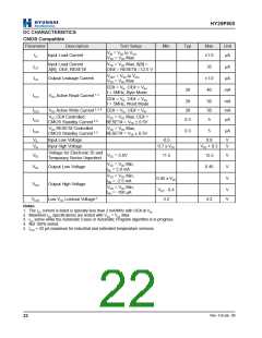
TEST CONDITIONS
+ 5V
Table 7. Test Specifications
- 70
- 55 - 90 Unit
- 12
Test
Condition
2.7
KOhm
Output Load
1 TTL Gate
DEVICE
UNDER
TEST
Output Load Capacitance (CL)
Input Rise and Fall Times
Input Signal Low Level
30
5
100
20
pF
ns
V
All diodes
are
1N3064
or
equivalen
0.0
3.0
0.45
2.4
6.2
KOhm
C L
Input Signal High Level
V
Low Timing Measurement
Signal Level
1.5
1.5
0.8
2.0
V
V
High Timing Measurement
Signal Level
Figure 11. Test Setup
3.0 V
I
nput
1.5 V
Measurement Level
1.5 V
Output
0.0 V
2.4 V
HY29F800-55 Version
2.0 V
2.0 V
0.8 V
Measurement
Levels
Input
Output
0.8 V
0.45 V
HY29F800-70, -90, -12 Versions
Figure 12. Input Waveforms and Measurement Levels
Rev. 4.0/Jan. 00
23

 ETC [ ETC ]