APEX 20K Programmable Logic Device Family Data Sheet
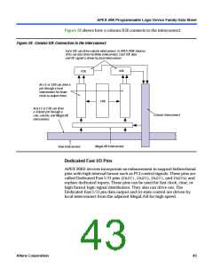
APEX 20KE devices also support the MultiVolt I/ O interface feature. The
APEX 20KE VCCINTpins must always be connected to a 1.8-V power
supply. With a 1.8-V VCCINT level, input pins are 1.8-V, 2.5-V, and 3.3-V
tolerant. The VCCIOpins can be connected to either a 1.8-V, 2.5-V, or 3.3-V
power supply, depending on the I/ O standard requirements. When the
VCCIOpins are connected to a 1.8-V power supply, the output levels are
compatible with 1.8-V systems. When VCCIOpins are connected to a 2.5-V
power supply, the output levels are compatible with 2.5-V systems. When
VCCIOpins are connected to a 3.3-V power supply, the output high is
3.3 V and compatible with 3.3-V or 5.0-V systems. An APEX 20KE device
is 5.0-V tolerant with the addition of a resistor.
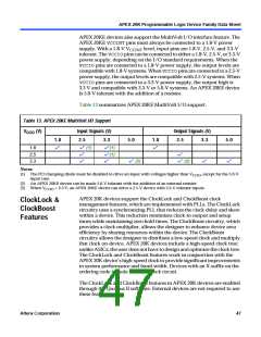
Table 13 summarizes APEX 20KE MultiVolt I/ O support.
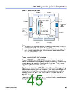
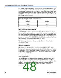
Table 13. APEX 20KE MultiVolt I/O Support
CCIO (V) Input Signals (V)
V
Output Signals (V)
1.8
2.5
3.3
5.0
1.8
2.5
3.3
5.0
1.8
2.5
3.3
v
v (1)
v
v(1)
v(1)
v
v
v
v
v (2)
v (2)
v
v
Notes:
(1) The PCI clamping diode must be disabled to drive an input with voltages higher than V
input case.
, except for the 5.0-V
CCIO
(2) An APEX 20KE device can be made 5.0-V tolerant with the addition of an external resistor.
(3) When V = 3.3 V, an APEX 20KE device can drive a 2.5-V device with 3.3-V tolerant inputs.
CCIO
APEX 20K devices support the ClockLock and ClockBoost clock
management features, which are implemented with PLLs. The ClockLock
circuitry uses a synchronizing PLL that reduces the clock delay and skew
within a device. This reduction minimizes clock-to-output and setup
times while maintaining zero hold times. The ClockBoost circuitry, which
provides a clock multiplier, allows the designer to enhance device area
efficiency by sharing resources within the device. The ClockBoost
circuitry allows the designer to distribute a low-speed clock and multiply
that clock on-device. APEX 20K devices include a high-speed clock tree;
unlike ASICs, the user does not have to design and optimize the clock tree.
The ClockLock and ClockBoost features work in conjunction with the
APEX 20K device’s high-speed clock to provide significant improvements
in system performance and band-width. Devices with an X-suffix on the
ordering code include the ClockLock circuit.
ClockLock &
ClockBoost
Features
The ClockLock and ClockBoost features in APEX 20K devices are enabled
through the Quartus II software. External devices are not required to use
these features.
Altera Corporation
47

 ETC [ ETC ]