Si3210/Si3211/Si3212
Linefeed Architecture
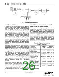
Loop Voltage and Current Monitoring
The ProSLIC is a low-voltage CMOS device that uses The ProSLIC continuously monitors the TIP and RING
low-cost external components to control the high voltages and external BJT currents. These values are
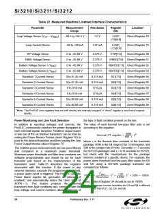
voltages required for subscriber line interfaces. available in registers 78–89. Table 22 on page 24 lists
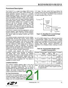
Figure 15 is a simplified illustration of the linefeed the values that are measured and their associated
control loop circuit for TIP or RING and the external registers. An internal A/D converter samples the
components used.
measured voltages and currents from the analog sense
circuitry and translates them into the digital domain. The
A/D updates the samples at an 800 Hz rate. Two
derived values are also reported—loop voltage and loop
The ProSLIC uses both voltage and current sensing to
control TIP and RING. DC and AC line voltages on TIP
and RING are measured through sense resistors R
DC
current. The loop voltage, V – V
, is reported as a
TIP
RING
and R , respectively. The ProSLIC uses linefeed
AC
1-bit sign, 6-bit magnitude format. For ground start
operation the reported value is the RING voltage. The
transistors Q and Q to drive TIP and RING. Q
P
N
DN
isolates the high-voltage base of Q from the ProSLIC.
N
loop current, (I – I + I –I )/2, is reported in a 1-
Q1
Q2
Q5 Q6
The ProSLIC measures voltage at various nodes in
order to monitor the linefeed current. R , R , and
bit sign, 6-bit magnitude format. In RING open and TIP
open states the loop current is reported as (I – I ) +
DC
SE
Q1
Q2
R
provide access to these measuring points. The
BAT
(I –I ).
Q5 Q6
sense circuitry is calibrated on-chip to guarantee
measurement accuracy with standard external
component tolerances. See "Linefeed Calibration" on
page 26 for details.
Linefeed Operation States
The ProSLIC linefeed has eight states of operation as
shown in Table 21. The state of operation is controlled
using the Linefeed Control register (direct Register 64).
The open state turns off all currents into the external
bipolar transistors and can be used in the presence of
fault conditions on the line and to generate Open Switch
Intervals (OSIs). TIP and RING are effectively tri-stated
with a dc output impedance of about 150 kΩ. The
ProSLIC can also automatically enter the open state if it
detects excessive power being consumed in the
external bipolar transistors. See "Power Monitoring and
Line Fault Detection" on page 24 for more details.
In the forward active and reverse active states, linefeed
circuitry is on and the audio signal paths are powered
down.
In the forward and reverse on-hook transmission states
audio signal paths are powered up to provide data
transmission during an on-hook loop condition.
The TIP Open state turns off all control currents to the
external bipolar devices connected to TIP and provides
an active linefeed on RING for ground start operation.
The RING Open state provides similar operation with
the RING drivers off and TIP active.
The ringing state drives programmable ringing
waveforms onto the line.
22
Preliminary Rev. 1.11

 ETC [ ETC ]