PRELIMINARY
PCT1789W DATA SHEET
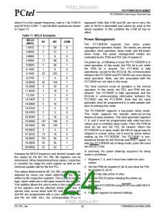
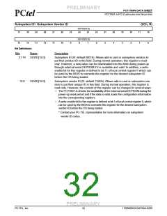
PCT789T-A BASE I/O LOCATIONS
!!
PCT789T-A BASE I/O LOCATIONS
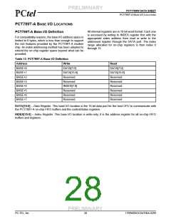
All internal registers are in 16-bit word format. Each one
is accessed by writing to INDEX register first with the
appropriate index address then read or write to the
addressed register through the DATA port. The index
range allocated for on-chip registers is from index 0
through 15.
PCT789T-A Base I/O Definition
For compatibility reasons, the base I/O address space is
limited to 8 bytes, which is less than enough to support
the rich features provided by the PCT789T-A modem
chip. An index addressing method has been adopted to
extend the on-chip register space beyond what can be
provided.
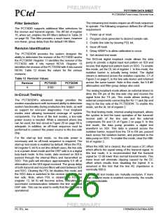
Table 13 PCT789T-A Base I/O Definition
Address
BASE+0
BASE+1
BASE+2
BASE+3
BASE+4
BASE+5
BASE+6
BASE+7
Write
Read
DATA[7:0]
DATA[15:8]
Reserved
Reserved
INDEX[7:0]
Reserved
Reserved
Reserved
DATA[7:0]
DATA[15:8]
Reserved
Reserved
Reserved
Reserved
Reserved
Reserved
DATA[15:0] – Data Register. This base I/O location is the 16-bit data port for the host CPU to communicate with
the PCT789T-A on-chip FIFO buffers and the control/status registers.
INDEX[15:0] – Index Register. This base I/O location is write-only; it is the address register for all on-chip FIFO
buffers and registers.
PRELIMINARY
PC-TEL, Inc.
28
1789W0DOCDAT06A-0299

 ETC [ ETC ]