PCT2303N DATA SHEET
CONTROL REGISTERS
!!
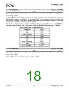
Line 1 DAC/ADC Rate
(Register 40h, R/W)
SR[15:0]
15
14
13
12
11
10
9
8
7
6
5
4
3
2
1
0
Reset settings = 0000h
Each DAC/ADC pair is governed by a read/write modem sample rate control register that contains a 16-bit unsigned
value between 0 and 65535, representing the rate of operation in Hz. A number written over 2EE0h causes the
sample rate to 13.714 kHz. For all rates, if the value written to the register is supported, that value is echoed back
when read, otherwise the closest rate supported is returned.
When set to zero, the internal PLL is disabled. The PLL should be programmed before the line-side (PCT303L) is
activated through clearing any PR bit in register 3Eh. Sleep mode is not supported when the PLL is disabled.
Table 5 Sample rates for Line 1 and Line 2
Sample Rate
7200
D[15:0]
1C20h
1F40h
2024h
20D0h
2328h
2580h
282Dh
2EE0h
3592h
8000
8228.57 (57600/7)
8400
9000
9600
10285.71 (72000/7)
12000
13714.28 (96000/7)
Line 2 DAC/ADC Rate
(Register 42h, R/W)
SR[15:0]
15
14
13
12
11
10
9
8
7
6
5
4
3
2
1
0
Reset settings = 0000h
Sample rates for line 2 are the same as for line 1, refer to Table 5.
PC-TEL, Inc.
18
2303N0DOCDAT10A-0899

 ETC [ ETC ]