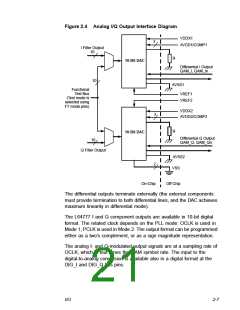
Figure 2.4 Analog I/Q Output Interface Diagram
VDDX1
3
AVDD1/COMP1
I Filter Output
10
R
10-Bit DAC
Differential I Output
QAM_I, QAM_In
10
AVSS1
Functional
Test Bus
(Test mode is
selected using
FT mode pins)
VREF1
VREF2
VDDX2
3
AVDD2/COMP2
R
10-Bit DAC
Differential Q Output
QAM_Q, QAM_Qn
10
Q Filter Output
AVSS2
VSS
2
On-Chip
Off-Chip
The differential outputs terminate externally (the external components
must provide termination to both differential lines, and the DAC achieves
maximum linearity in differential mode).
The L64777 I and Q component outputs are available in 10-bit digital
format. The related clock depends on the PLL mode: OCLK is used in
Mode 1; PCLK is used in Mode 2. The output format can be programmed
either as a two’s complement, or as a sign magnitude representation.
The analog I- and Q-modulated output signals are at a sampling rate of
OCLK, which is four times the QAM symbol rate. The input to the
digital-to-analog conversion is available also in a digital format at the
DIG_I and DIG_Q bus pins.
I/O
2-7

 ETC [ ETC ]