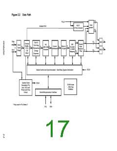
Figure 2.2 Data Path
10
10
PCLK
Inter-
polator*
NCO*
& freq compare
divided ICLK
t
I
I
Data
10
10
DAC
DAC
I
Sync &
Error flag
Reinsertion
Energy
1
Circular
Buffer
FIFO
128
Square
Diff.
RS
8
Input
Sync
Stage
m
Convol.
Interleaver
Byte to
m-tuple
8
8
8
8
Root
Nyquist
Filter
Encoder
& QAM
Mapping
(204,188)
8
Q
Encoder
ICLK
Q
Q
Word
Dispersal
Global Control and Synchronization - Start/Stop Signals Generation
OCLK
Symbol Clock
OCLK
SCAN chain
JTAG Test
RAMbist
Generation PLL
(incl. VCO and
Phase and Freq.
Comp.)
Serial Microprocessor Interface
* Only used in PLL Mode 2
SCL
SDA
-23

 ETC [ ETC ]