On ATM networks, you must prebuffer input data to get a continuous
frame rate at the chip input. If high input jitter occurs over an ATM without
a prebuffer, the whole PLL regulation of the input-to-output frame rate
fails. You must design the size of the prebuffer according to the maximum
jitter expected over the asynchronous transfer mode (ATM) network.
2.3 I/O
The following subsections describe the input and output of the L64777.
2.3.1 Input
The QAM Modulator accepts serial input data at a maximum 54 MHz
clock frequency on the ICLK pin. In Byte-Parallel Input mode (Parallel
mode), the maximum frequency on ICLK is 10 MHz. DVALIDIN
distinguishes between valid and invalid input data on DIN[7:0]. ERRORIN
marks incorrect packets in the transport header, in case a preceding
device passes erroneous information. The input error flag is transferred
into the TRANSPORT_ERROR_INDICATOR bit of MPEG transport
packets. Either the FSTARTIN pulse or the SYNC_BYTE detection (0x47
for MPEG transport packets) establishes input synchronization.
The FSTARTIN pulse marks the first bit, the most significant bit of an
MPEG SYNC_BYTE in Serial Input mode (Serial mode), or the
SYNC_BYTE in Parallel mode. The FSTARTIN pulse synchronizes the
process of forming bytes from bits in Serial mode. If no such
synchronization signal is applied, the input synchronizer searches for the
programmed SYNC_BYTE occurring in the programmed sync length. In
Parallel mode, the L64777 assumes the byte boundaries are correct and
compares the SYNC_BYTE in parallel to the incoming bytes. A flywheel
circuit stabilizes the synchronization to a SYNC_BYTE, while
synchronization by external pulses feeds directly into the internal control
circuits (see Section 2.4, “Input Synchronization,” page 2-10).
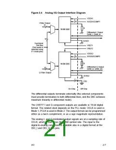
2.3.2 Output Signals
The L64777 outputs the I and Q components of its signal on two
separate analog output interfaces (see Figure 2.4). The output interface
contains two internal 10-bit digital-to-analog converters.
2-6
Modulator Architecture

 ETC [ ETC ]