AN-35
The division by two in the expression for PCORE is required since
a flyback transformer only excites the core asymmetrically and
the core loss curves are typically specified assuming a
symmetrical excitation.
OnceanestimateforthenumberofsecondaryturnsNS hasbeen
made, the primary turns is found from:
VOR
(15)
NP =
× NS
VSEC
KCORE is then read directly from material core loss curves at the
LinkSwitch switching frequency (typically 42 kHz). A figure
for BM of approximately 3300 gauss (330 mT) is a good initial
estimate. A figure for PCORE of 0.1 W is a good initial estimate.
100
80
PO(EFF) is calculated from:
P
CORE
P
= P + P
)
+ P
+ P + P
+
O
CABLE
DIODE
BIAS
S(CU)
O EFF
(
Area compensated
2
by ∆L term
(13)
PO here is defined as the output power seen by the load. Note
the core loss term is divided in half as only the loss associated
with transferring energy to the output during the off time needs
to be compensated for in the primary inductance value.
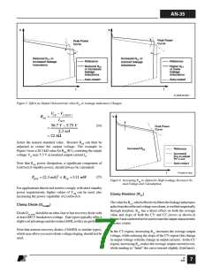
250 330
Flux Density (mT)
PI-3148-081502
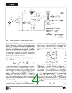
Figure 4. Typical Reduction in Primary Inductance with Flux
Density for Small E Cores with Small Gap Sizes.
Nominal primary inductance LP(NOM) is calculated from:
2 × P
O EFF
(
)
LP(NOM)
=
× ∆L
(14)
At this point the core size should be selected. Common core
sizes suitable for a LinkSwitch design include EE13, EF12.6,
EE16 and EF16. With the core selected and the number of
transformer turns known, the core peak flux density BP (gauss)
can be found using the effective cross sectional area of the core
Ae (cm2), the primary inductance (µH) and the LinkSwitch peak
current limit ILIM(MAX) (A):
IP2 × fS
[
]
ThetypicaldatasheetvaluefortheI2fcoefficientshouldbeused
to replace IP2fS, this defining the nominal primary inductance at
the nominal output peak power point.
As the flux density increases, the inductance falls slightly due
to the BH characteristic of the core material as shown in
Figure 4. This drop in inductance is compensated by increasing
the inductance at zero flux density by a factor ∆L. This is
typically in the range of 1 to 1.05 for common low cost ferrite
materials. This effect can be minimized by increasing the gap
size, reducing the flux density or using ferrite materials with a
higher saturation flux density.
100 × ILIM(MAX) × LP
(16)
BP =
NP × Ae
BP should be in the range of 3000 gauss to 3500 gauss
(300 mT to 350 mT).
The relative permeability µr of the ungapped core must be
calculated to estimate the gap length Lg. The relative
permeability, µr is found from core parameters Ae (cm2), the
effective core path length Le (cm), and ungapped effective
inductance AL(nH/t2):
Transformer inductance tolerance is most affected by the
transformer core gap length. Inductance must also be stable
over temperature and as a function of current. Recommended
minimumgaplengthis0.08mm(3.2mils)atapeakfluxdensity
of 3300 gauss to 3500 gauss (330 mT to 350 mT).
AL × Le
0.4 × π × Ae ×10
µr =
(17)
The number of secondary turns for small E cores is typically 2
to 3 turns per volt across the secondary winding (including
cable, secondary and diode voltage drops). The actual number
is adjusted to meet gap size and flux density limits.
Gap length Lg is the air gap ground into the center leg of the
transformer core. Grinding tolerances and AL accuracy place a
minimumlimitofapproximately0.08mmonLg.If Lg issmaller
than this then either the core size (Ae) or NP must be increased.
Lg (mm) is calculated from primary turns NP, core effective
B
4/03
5

 ETC [ ETC ]