AN-35
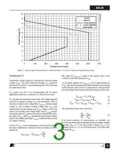
10
9
115 VAC
230 VAC
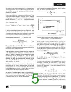
Limits (LNK501)
Limits (LNK500)
Auto-restart
8
7
6
5
4
3
2
1
0
0
100
200
300
400
500
600
700
Output Current (mA)
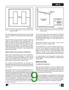
Figure 2. Typical Output Characteristic for LinkSwitch Based 5.5 V, 0.5 A Charger with Specification Limits.
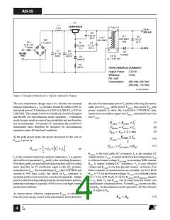
Transformer T1
The value for IPRI(PEAK) is equal to the typical value of the
LinkSwitch data sheet parameter ILIM
.
Transformer design begins by selecting the reflected output
voltage (VOR). For most LinkSwitch designs, VOR should be
between 40 V and 60 V. A good starting point is 50 V allowing
for optimization later.
As an initial estimate the ISEC(PEAK) can be approximated as
4 xIO. Once the first prototype has been built this can be refined
as the final turns ratio is known or alternatively, the peak diode
forwardvoltagecanbemeasureddirectlyusinganoscilloscope.
VOR values over 60 V are recommended only for those
applications allowed to consume over 300 mW at no-load.
VRCABLE = IO × RCABLE
(2)
To calculate the transformer turns ratio, the voltage required
across the secondary winding VSEC is first calculated. This is a
function of output cable voltage drop VRCABLE, nominal output
VRSEC = ISEC(PEAK) × RSEC
VSEC = VO + VRCABLE + VDOUT + VRSEC
(3)
(4)
voltage VO, the secondary winding voltage drop VRSEC, and
output diode forward voltage drop VDOUT. Figure 1 shows the
sources of secondary side voltage drops. Since CCLAMP charges
tothepeakvalueofVOR plusanerrorduetoleakageinductance,
the value of VRSEC and VDOUT are defined at the peak secondary
current. The output cable drop VRCABLE is defined at the nominal
CC output current IO.
The transformer turns ratio is given by:
NP VOR
(5)
=
NS VSEC
If no better estimates or measurements are available, use
0.15Ωasaninitialvalueforthetransformersecondarywinding
resistance RSEC, 0.7 V for the forward voltage (VDOUT) of a
Schottky diode or 1.1 V for a PN diode and 0.3 Ω for the cable
Curves of VDOUT versus instantaneous current can be found in
the diode manufacturer’s data sheet. Peak secondary current is
defined as:
resistance RCABLE
.
NP
ISEC(PEAK) = IPRI(PEAK)
×
(1)
NS
B
4/03
3

 ETC [ ETC ]