ZENTRUM MIKROELEKTRONIK DRESDEN AG
“ASI for you” IC
Datasheet
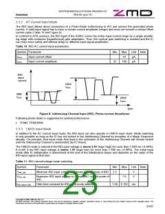
The following input levels apply in CMOS mode:
Table 12: IRD CMOS Input Levels
Symbol
VIRD_IN
VIRD_IL
VIRD_IH
Tr /Tf
Parameter
Min
-0.3
0
Max
VUout
1.0
Unit Note
Input voltage range
V
V
V
Voltage range for input ”low” level
Voltage range for input ”high” level
Rise/fall time
2.5
VUout
1
100
ns
1 in Master Mode the rise/fall time of the IRD input signal should be as low as possible in order to avoid jitter on
the AS-i line
3.3.4 Master-, Repeater- and Monitor-Mode
In Master-, Repeater-, and Monitor-Mode the IRD input is always configured in CMOS mode. The input levels
specified in Table 12 apply.
The expected polarity of the Manchester-II-coded bit stream at the IRD pin depends on the values of the Pins
DI0 and DI1.
Table 13: Polarity of Manchester-II-Signal at IRD in Master Mode
Input values at
Description
DI0 and DI1 are:
Equal
(“11”, “00”)
Manchester-II-Signal is low active (default logic output value at no communica-
tion is ‘1’). This mode is compatible to the A²SI IRD input
Unequal
(“01”, “10”)
Manchester-II-Signal is high active (default logic output value at no communica-
tion is ‘0’).
Note: The complemented definition was chosen to retain backward compatibility to A²SI based AS-i Master de-
signs.
Copyright © 2006, ZMD AG, Rev.1.4
All rights reserved. The material contained herein may not be reproduced, adapted, merged, translated, stored, or used without the prior written consent of the copyright owner. The
Information furnished in this publication is preliminary and subject to changes without notice.
24/57

 ZMD [ Zentrum Mikroelektronik Dresden AG ]