ZENTRUM MIKROELEKTRONIK DRESDEN AG
“ASI for you” IC
Datasheet
3.3.2 AC Current Input Mode
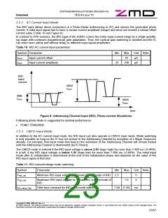
The IRD input allows direct connection of a Photo-Diode (referencing to 0V) and senses the generated photo
current. A valid input signal has to have a certain current amplitude (range) and must not exceed a certain offset
current value (Table 10 and Figure 8).
In contrast to A²SI versions, the IRD input of the ASI4U covers the entire input current range by a single amplify-
ing stage with continues (logarithmical) gain adaptation. Thus, the cyclical gain switching is avoided and the IC
can react more safely and without delay on different input signal amplitudes.
Table 10: IRD AC current input parameters
Symbol Parameter
IIRDO Input current offset
IIRDA Input current amplitude
Min
25
Max
10
Unit Note
µA
µA
100
IRD
input
current
MAX
IIRDA
MIN
IIRDA
MAX
IIRDO
time
Figure 8: Addressing Channel Input (IRD), Photo-current Waveforms
Following photo-diode is suggested for optimal performance:
• TEMIC TEMD5000
3.3.3 CMOS Input Mode
In addition to the AC current input mode, the IRD input can also operate in CMOS input mode. Mode switching
is only possible as long as the IC has not locked to the Addressing Channel by reception of a Magic Sequence
already. On principle, that input mode that lead to the activation of the Addressing Channel will remain locked
until the Addressing Channel is deactivated (by IC Reset).
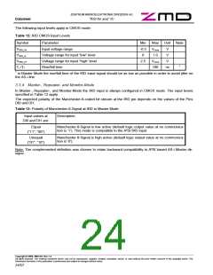
The CMOS mode is entered if the IRD input voltage is above 2.5V (logic high) for more than 7.680 ms (-6.66%).
It is left, if the IRD input voltage is below 1.0V (logic low) for more than 7.680 ms (-6.66%). The initial input
mode after IC initialization is determined at the end of the initialization phase and depends on the value of the
IRD input signal at that time.
Table 11: IRD current/voltage mode switching
Symbol
VIRD_VM
VIRD_CM
Parameter
Min
2.5
Max
1.0
Unit Note
Minimum IRD input voltage to activate CMOS mode of IRD
V
V
Maximum IRD input voltage to activate AC current mode of
IRD
tIRD_Mode_Filter
Filter time constant for IRD input mode switching
7.68 8.192 ms
Copyright © 2006, ZMD AG, Rev.1.4
All rights reserved. The material contained herein may not be reproduced, adapted, merged, translated, stored, or used without the prior written consent of the copyright owner. The
Information furnished in this publication is preliminary and subject to changes without notice.
23/57

 ZMD [ Zentrum Mikroelektronik Dresden AG ]