ZENTRUM MIKROELEKTRONIK DRESDEN AG
“ASI for you” IC
Datasheet
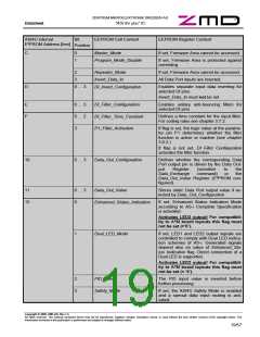
ASI4U internal
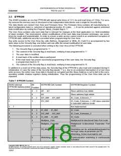
Bit
Position
EEPROM Cell Content
EEPROM Register Content
E²PROM Address [hex]
C
0
1
Master_Mode
If set, Firmware Area cannot be accessed.
Program_Mode_Disable
If set, Firmware Area is protected against
overriding.
2
Repeater_Mode
If set, Firmware Area cannot be accessed.
All Data Port inputs are inverted.
3
Invert_Data_In
D
0 … 3
DI_Invert_Configuration
Enables separate input data inverting for
selected DI pins.
Invert_Data_In must not be set.
E
F
0 … 3
0 … 2
3
DI_Filter_Configuration
DI_Filter_Time_Constant
P1_Filter_Activation
Enables unitary anti-bouncing filters for
selected DI pins
Defines a time constant for the input filter.
For coding rules see chapter 3.7.2.
If flag is set, the logic value at the parame-
ter pin P1 determines whether the filter
function is active or inactive (see chapter
3.6.2.)
If flag is not set, DI_Filter_Configuration
activates the filter function.
10
0 … 3
Data_Out_Configuration
Defines whether the corresponding Data
Port output pin is driven by the Data Out-
put
Register
(sensitive
to
or
the
the
Data_Exchange
command)
Data_Out_Value Register (E²PROM con-
figured).
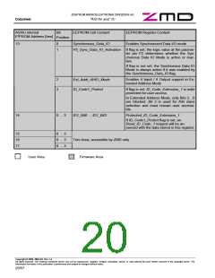
11
12
0 … 3
0
Data_Out_Value
Stores static Data Port output value if se-
lected by Data_Out_Configuration
Enhanced_Status_Indication
If set, Enhanced Status Indication Mode
according to AS-i Complete Specification
is activated.
Activates LED2 output! For compatibil-
ity to A²SI board layouts this flag must
not be set (=‘0’).
1
Dual_LED_Mode
If set, LED1 and LED2 output signals are
controlled to comply with Dual LED indica-
tion schemes of AS-i. Generated signals
depend also on value of Enhanced_Sta-
tus_Indication flag. Direct connection of a
Dual LED is supported.
Activates LED2 output! For compatibil-
ity to A²SI board layouts this flag must
not be set (= ‘0’).
2
3
FID_Invert
The FID input value is inverted before
further processing
Safety_Mode
If set, the ASI4U Safety Mode is enabled
and a special data input routing is acti-
vated.
Copyright © 2006, ZMD AG, Rev.1.4
All rights reserved. The material contained herein may not be reproduced, adapted, merged, translated, stored, or used without the prior written consent of the copyright owner. The
Information furnished in this publication is preliminary and subject to changes without notice.
19/57

 ZMD [ Zentrum Mikroelektronik Dresden AG ]