ZENTRUM MIKROELEKTRONIK DRESDEN AG
“ASI for you” IC
Datasheet
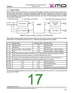
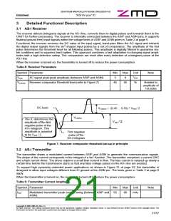
2.4 Master Mode
Master Mode and the related Repeater- and Monitor-Modes differ completely in their functional properties from
the Slave Mode. While the IC can autonomously perform different tasks in Slave Mode, it will only act as physi-
cal layer transceiver in Master-, Repeater- and Monitor-Mode. The basic property of these modes is a modula-
tion / demodulation of AS-i signals to Manchester-II-code and vice versa. The following figure shows the differ-
ent data path configurations.
Master Mode
Slave Mode, ASI-Channel
Slave Mode, IRD Addressing Channel
ASI+
ASI-
IRD CMOS
Input
IRD
ASI- Receiver
(TX)
UART
LED1
(RX)
ASI- Transmitter
LED Output
Figure 6: Data path in Master-, Repeater- and Monitor-Mode
Master-Mode, Repeater-Mode and Monitor-Mode differ from each other in the kind of signals that are available
at the data I/O and parameter port pins of the IC. Following signal assignments are provided:
Pin
P0
Master Mode
Repeater Mode
Monitor Mode
Receive Clock
Power Fail
Hi-Z
Hi-Z
Hi-Z
Hi-Z
Receive Clock
P1
Power Fail
P2
Receive Strobe – Slave Telegram
Hi-Z
Receive Strobe – Slave Telegram
Receive Strobe – Master Telegram
P3
DI0
DI1
DI2
DI3
DO0
DO1
DO2
DO3
Inverting of IRD input signal. If both inputs are on different level, the IRD input signal is inverted
before further processing, otherwise it is directly forwarded to the UART.
Inverting of LED output signal. If both inputs are on different level, the LED output signal is in-
verted after processing, otherwise it is directly forwarded to the LED1 output.
Hi-Z
Hi-Z
Hi-Z
Hi-Z
Hi-Z
Hi-Z
Hi-Z
Hi-Z
Pulse Code Error
No Information Error
Parity Bit Error
Manchester-II-Code Error at IRD Input
More detailed signal descriptions can be found in chapters 3.6 Parameter Port and PST, 3.7 Data Port and DSR
as well as 3.12 UART.
Copyright © 2006, ZMD AG, Rev.1.4
All rights reserved. The material contained herein may not be reproduced, adapted, merged, translated, stored, or used without the prior written consent of the copyright owner. The
Information furnished in this publication is preliminary and subject to changes without notice.
17/57

 ZMD [ Zentrum Mikroelektronik Dresden AG ]