ZENTRUM MIKROELEKTRONIK DRESDEN AG
“ASI for you” IC
Datasheet
3.3 Addressing Channel Input IRD
3.3.1 General Slave Mode Functionality
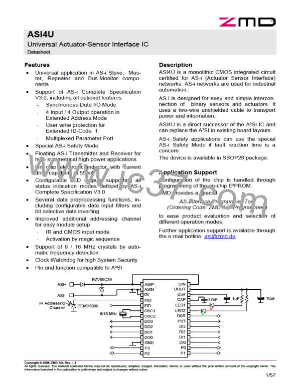
To ease the configuration process for slave modules at the field application, a secondary command input chan-
nel, the so-called Addressing Channel, IRD, is provided.
Once the channel is activated for communication, the IRD pin is receiving Manchester-II-coded (AS-i) master
telegrams, while the LED1 pin is returning slave response telegrams in Manchester-II format.
Applying a so-called Magic Sequence at the IRD input activates the Addressing Channel. It doesn’t matter
whether the IC is communicating at the AS-i input channel or staying in idle mode. As long as the initialization
process is finished and the IC is operating in Slave Mode, a correctly received Magic Sequence will reset the
Data and Parameter Outputs, generate appropriate Data Strobe and Parameter Strobe signals, reset the
Data_Exchange_Disable flag and turn the Addressing Channel active.
The Magic Sequence requires the reception of four consecutive correct AS-i telegrams in Manchester-II-Format
within a timeframe of 8.192 ms (-6.25%). The telegrams will neither be answered nor otherwise internally proc-
essed. They are only checked for correct syntax (number of bits, correct start bit, end bit and parity) and timing
(compliance to standard AS-i telegram timing).
To avoid a wrong activation of the Addressing Channel by undesired cross coupling of signals from the AS-i line
to the IRD input, two additional security features are implemented.
1. The ASI4U resets the Magic Sequence telegram counter if more than 5 but less than 14 telegram bits
were correctly received. Pulse signals that lead to detection of a communication error before the 6th
telegram bit shall not reset the Magic Sequence counter in order to avoid a blocking of the IRD activa-
tion due to signal bouncing effects.
2. The ASI4U resets the Magic Sequence telegram counter if a telegram that was received at the IRD in-
put correlates to the AS-i line input signal in terms of telegram reception time and content.
Note: The UART processes both input channels (AS-i line + IRD Addressing Channel) in parallel and gen-
erates Receive_Strobe signals after every correctly received Master telegram. A telegram correlation be-
tween both channels is found, if Receive_Strobe signals from both input channels arrive at a time frame of
less or equal than 3µs and the telegram contents are equal too.
The Addressing Channel generally becomes deactivated by IC reset.
If the IC is locked to the Addressing Channel and AC Current Input Mode (see descriptions further below) is
active, there are four special IC functions that were implemented to support existing handheld programming
devices (from the company Pepperl+Fuchs):
1. The IC does not leave the Addressing Channel Mode after the reception of a Reset_Slave or Broad-
cast_Reset call if the Data_Exchange_Disable flag is cleared (‘0’). This is always the case if the ASI4U
had performed Data-/Parameter communication in advance of the reset. Thus the handheld had been
operated in Data- or Parameter mode.
2. The IC does not leave the Addressing Channel during an IC reset that was caused by an expired Com-
munication Watchdog.
See chapter 3.14 for detailed descriptions of the Communication Monitor and Communication Watch-
dog.
3. Software controlled IC resets (resets through Reset_Slave or Broadcast_Reset calls) are performed
slightly different than in normal slave IC operation.
The IC still resets the Data and Parameter outputs immediately after reception of the calls and Data-
and Parameter-Strobe Signals are generated. However, the IC initialization procedure is postponed for
2.048ms (-6.25%), keeping the IC blocked to any further telegram inputs at the Addressing Channel or
the AS-i line input. This is to avoid an immediate reactivation of the Addressing Channel after IC initiali-
zation since the handheld programming device always sends five subsequent Broadcast_Reset. The
ASI4U would otherwise process the first reset call from the handheld correctly but take the four remain-
ing calls for a new Magic Sequence.
4. The UART is constantly set to Synchronous Receive Mode. This is because the signal sequence, that
is generated by the handheld programming device, exhibits an additional signal transition in a time
frame of 3 bit times after the end of the transmitted master call.
Copyright © 2006, ZMD AG, Rev.1.4
All rights reserved. The material contained herein may not be reproduced, adapted, merged, translated, stored, or used without the prior written consent of the copyright owner. The
Information furnished in this publication is preliminary and subject to changes without notice.
22/57

 ZMD [ Zentrum Mikroelektronik Dresden AG ]