ZENTRUM MIKROELEKTRONIK DRESDEN AG
“ASI for you” IC
Datasheet
The multiplexed transfer of course increases the refresh time per output by a factor of two, however, some ap-
plications can tolerate this increase for the benefit of less external circuitry and better slave address efficiency.
The sampling cycle of the data inputs remains unchanged since the meaning of I3 bit was not changed in the
slave response with the definition of the Extended Address Mode.
More detailed information is described in chapter 3.7.5 Support of 4I/4O processing in Extended Address Mode,
Profile 7.A.x.E on page 34.
2.3.10 AS-i Safety Mode
The enhanced data input features described above require additional registers in the data input path that store
the input values for a certain time before they hand them over to the AS-i transmitter. This causes a time delay
in the input path that could lead to a delayed “turn off” event, if the registers were activated by intention or by
accident in AS-i Safety Applications.
To safely exclude an activation of the enhanced data I/O features in Safety Applications, the IC provides a spe-
cial Safety Mode that is strongly recommended to be used for AS-i Safety communication purposes. See chap-
ter 3.7.6 Safety Mode Operation on page 34 for further details.
2.3.11 Enhanced LED Status Indication
ASI4U newly supports enhanced status indication by two LED outputs. A special mode for direct application of
Dual-LEDs and the respective different signaling modes is also implemented. Compared to the A²SI, the former
U5RD pin was reassigned as LED2 pin. Thus, compatibility to existing A²SI board layouts is still guaranteed.
However, it will require to keep LED2 pin disabled (default state at delivery) in order to avoid short-circuiting of
U5R to ground. More detailed information on the different signaling schemes and their activation can be found in
chapter 3.9 LED outputs on page 40.
2.3.12 Communication Monitor/Watchdog
Data and Parameter communication are continuously observed by a communication monitor. If neither
Data_Exchange nor Write_Parameter calls were addressed to and received by the IC within a time frame of
about 41ms, a so called No Data/Parameter Exchange status is detected and signaled at LED1.
If the respective flags are set in the E²PROM the communication monitor can also act as communication watch-
dog, that initiates a complete IC reset after expiring of the watchdog timer. The watchdog mode can also be
activated and deactivated by a signal at parameter port pin P0. For more detailed information see chapter 3.14
Communication Monitor/Watchdog on page 47.
2.3.13 Write protection of ID_Code_Extension_1
As defined in AS-i Complete Specification v3.0 the ASI4U also supports write protection for ID_Code_Exten-
sion_1. The feature allows the activation of new manufacturer protected slave profiles and is enabled by
E²PROM setting. It is described in more detail in chapter 3.16 Write Protection of ID_Code_Extension_1 on
page 47
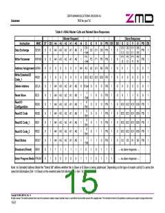
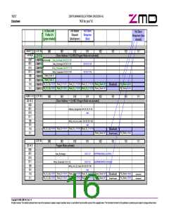
2.3.14 Summary of Master Calls
Table 6 on page 15 and the diagram at the following page show the complete set of Master Calls that are de-
coded by the ASI4U in Slave Mode. The "Enter Program Mode" call is intended for programming of the IC by
the slave manufacturer only. It becomes deactivated as soon as the Program_Mode_Disable flag is set in the
Firmware Area of the E²PROM.
AS-i Complete Specification compliance note:
In order to achieve full compliance to the AS-i Complete Specification, the Program_Mode_Disable flag must be
set by the manufacturer of AS-i slave modules during the final manufacturing and configuration process and
before an AS-i slave device is delivered to field application users.
Copyright © 2006, ZMD AG, Rev.1.4
All rights reserved. The material contained herein may not be reproduced, adapted, merged, translated, stored, or used without the prior written consent of the copyright owner. The
Information furnished in this publication is preliminary and subject to changes without notice.
14/57

 ZMD [ Zentrum Mikroelektronik Dresden AG ]