ZENTRUM MIKROELEKTRONIK DRESDEN AG
“ASI for you” IC
Datasheet
chapter 3.3 Addressing Channel Input IRD.
FID DIGITAL /
ANALOG
STAGE
Pin FID can be set to digital CMOS mode or analog voltage input mode. In Slave Mode it is
set to CMOS operation, in Master Mode it works in analog mode and acts as input for the
power fail comparator.
INPUT STAGE
All digital inputs, except of the oscillator pins, have high voltage capabilities and partly
Schmitt-Trigger and Pull-Up features. For more details see chapter 3.4 Digital Inputs - DC
Characteristics.
OUTPUT
STAGE
All digital output stages, except of the oscillator pins, have high voltage capabilities and are
implemented as NMOS open drain buffers. Each pin can sink up to 10mA of current.
2.2 General Operational Modes
The ASI4U provides two main and two additional sub operational modes. Main operation modes divide in
Slave Mode and Master Mode. Sub operation modes divide in Repeater Mode and Monitor Mode. The later
were derived from Master Mode in providing different output signals at the Parameter Port.
A definition of which operational mode becomes active is made by programming the flags Master_Mode and
Repeater_Mode in the Firmware Area of the E²PROM (see also Table 7 on page 18). The E²PROM is read out
at every initialization of the IC. Online mode switching is not provided. The following configurations apply:
Table 5: Assignment of operational modes
Selected Operational Mode
Slave Mode
Master Mode Flag Repeater Mode Flag
0
1
1
0
0
0
1
1
Master Mode
Repeater Mode
Monitor Mode
In Slave Mode the ASI4U operates as fully featured AS-i Slave IC according to AS-i Complete Specification
v3.0.
In Master Mode the ASI4U translates a digital output signal from the master control logic (etc. PLC, µP, …) to a
correctly shaped, analog AS-i pulse sequence and vice versa. Every AS-i telegram received is checked for con-
sistency with the AS-i communication protocol specifications and if no errors were found, an appropriate receive
strobe signal is generated.
Master Mode and Monitor Mode differ in the kind of signaled telegrams. In Master Mode a single Receive
Strobe signal is provided validating every correctly received Slave Response while in Monitor Mode two different
Receive Strobe signals are available displaying every correctly received Master and Slave telegram separately.
The Monitor Mode is intended for use in intelligent slaves and bus monitors that provide own telegram decoding
mechanisms but do not check for correct telegram timing or syntax.
The Repeater Mode is specifically provided for AS-i bus repeater applications.
2.3 Slave Mode
The Slave Mode is probably the most complex operational mode of the IC. The ASI4U does not only support all
mandatory AS-i Slave functions but also a variety of additional features that shall make AS-i Slave module de-
sign very easy and flexible.
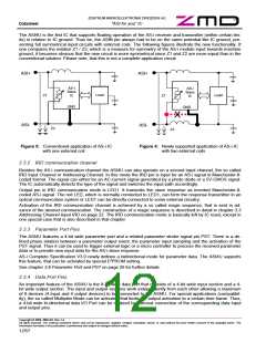
2.3.1 AS-i communication channel
In slave mode the ASI4U can work on two different communication channels, the AS-i channel and the IRD
channel. The AS-i channel is directly connected to AS-i Bus via the pins ASIP and ASIN. A receiver and a
transmitter unit are connected in parallel to the pins that allow fully bi-directional communication through ASIP
and ASIN.
Copyright © 2006, ZMD AG, Rev.1.4
All rights reserved. The material contained herein may not be reproduced, adapted, merged, translated, stored, or used without the prior written consent of the copyright owner. The
Information furnished in this publication is preliminary and subject to changes without notice.
11/57

 ZMD [ Zentrum Mikroelektronik Dresden AG ]