ZENTRUM MIKROELEKTRONIK DRESDEN AG
“ASI for you” IC
Datasheet
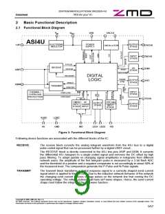
DIGITAL LOGIC The digital logic block contains UART, Main State Machine, E²PROM memory and other
control logic. E²PROM write access and other I/O operations of the Main State Machine are
supported in Slave Mode only (see description of general IC operational modes below). In
Master Mode the IC is basically equivalent to a physical layer transceiver.
If Slave Mode is activated, the UART demodulates the received telegrams, verifies telegram
syntax and timing and controls a register interface to the Main State Machine. After recep-
tion of a correct telegram, the UART generates appropriate Receive Strobe signals, that tell
the Main State Machine to start further processing. The Main State Machine decodes the
telegram information and starts respective I/O processes or E²PROM access. A second
register interface is used to send data back to the UART for construction of a telegram re-
sponse. The UART modulates the response data into a Manchester-II-coded bit stream that
is used to control the TRANSMIT unit.
ELECTRONIC
INDUCTOR
The electronic inductor is basically a gyrator circuit. It provides an inductive behavior be-
tween the IC pins UIN and UOUT while the inductance is controlled by the capacitor on pin
CAP. The inductor shall decouple the power regulator of the IC as well as the external load
circuit from the AS-i bus and hence prevent cross talk or switching noise from disturbing the
telegram communication on the bus.
The AS-i Complete Specification describes the input impedance behavior of a slave module
by an equivalent circuit that consists of R, L and C in parallel. For example, a slave module
in Extended Address Mode shall have R > 13.5 kOhm, L > 13.5 mH and C < 50pF. The
electronic inductor of the ASI4U delivers values that are well within the required ranges for
output currents up to 55mA. More detailed parameters can be found in chapter 3.17.2.
The electronic inductor requires an external capacitor of 10µF at pin UOUT for stability.
POWER
SUPPLY
The power supply block consists of a bandgap referenced 5V-regulator as well as other
reverence voltage and bias current generators for internal use. The 5V regulator requires an
external capacitor at pin U5R of at least 1µF for stability. It can source up to 4mA for exter-
nal use, however the power dissipation and the resulting device heating become a major
concern, if too much current is drawn from the regulator.
OSCILLATOR
The oscillator supports direct connection of 8.000 MHz or 16.000 MHz crystals with a dedi-
cated load capacity of 12pF and parasitic pin capacities of up to 8pF. The IC automatically
detects the oscillation frequency of the connected crystal and controls the internal clock
generator circuit accordingly.
After power-on reset the IC is set to 16.000 MHz operation by default. After about 200µs it
will either switch to 8.000 MHz operation or remain in the 16.000 MHz mode. The frequency
detection is active until the first AS-i telegram was successfully received in order to make
sure the IC found the correct clock frequency setting. The detection result is locked thereaf-
ter to increase resistance against burst or other interferences.
The oscillator unit also contains a clock watch dog circuit that can generate an uncondi-
tioned IC reset if there was no clock oscillation for more than about 20µs. This is to prevent
the IC from unpredicted behavior if no clock signal is available anymore.
THERMAL /
OVERLOAD
PROTECTION
The IC is self protected against thermal overheating and short circuiting of pin UOUT to-
wards IC ground.
If the silicon die temperature rises above around 140°C for more than 2 seconds, the IC
detects thermal overheating, switches off the electronic inductor, performs an IC reset and
sets all analog blocks to power down mode. The 5V-regulator is of course also turned off in
this state, however, there will still remain a voltage of about 3 … 3.5V available at U5R that
is derived from the internal start circuitry. The overheat protection state can only be left by
power-cycling the AS-i voltage.
Shortcutting pin UOUT towards IC ground leads to the same IC behavior as thermal over-
heating.
IRD CMOS /
AC CURRENT
INPUT
The IRD pin is input for the additional addressing channel in Slave Mode (see description of
General IC Operational Modes below) or direct AS-i transmitter input in Master Mode. In
Slave Mode it can be operated either in CMOS Mode or AC-current input mode. The later is
provided for direct connection of a photo diode. More detailed information can be found in
Copyright © 2006, ZMD AG, Rev.1.4
All rights reserved. The material contained herein may not be reproduced, adapted, merged, translated, stored, or used without the prior written consent of the copyright owner. The
Information furnished in this publication is preliminary and subject to changes without notice.
10/57

 ZMD [ Zentrum Mikroelektronik Dresden AG ]