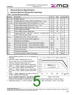
ZENTRUM MIKROELEKTRONIK DRESDEN AG
“ASI for you” IC
Datasheet
2
Basic Functional Description
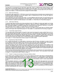
2.1 Functional Block Diagram
UIN
U5R
OSC1/2
UOUT
ASI4U
ELECTRONIC
INDUCTOR
POWER
SUPPLY
OUTPUT
STAGE
CAP
DO(3:0)
DI(3:0)
OSCILLATOR
INPUT
STAGE
P-PULSE
RECEIVE
I/O
DSR
PST
N-PULSE
RESET
ASIP
ASIN
STAGE
DATA-STRB
REC-RESET
DIGITAL
LOGIC
PARAM
STRB
OUTPUT
STAGE
SEND-D
TRANSMIT
SEND-SBY
INPUT
THERMAL /
OVERLOAD
PROTECTION
OVER-LOAD
OVER-HEAT
STAGE
P(3:0)
IRD_IN
CMOS
AC
DIG
ANA
OUTPUT
STAGE
OUTPUT
STAGE
INPUT Current
STAGE INPUT
INPUT
STAGE
AGND
LGND
0V
GND
IRD
LED1 LED2
FID
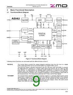
Figure 3: Functional Block Diagram
Following device functions are associated with the different blocks of the IC:
RECEIVE
The receive block converts the analog telegram waveform from the AS-i bus to a digital
pulse coded signal that can be processed further by a digital UART circuit.
The RECEIVE block is directly connected to the AS-i line pins ASIP and ASIN. It converts
the differential AS-i telegram to a single ended signal and removes the DC offset by high
pass filtering. To adapt quickly on changing signal amplitudes in telegrams from different
network users, the amplitude of the first telegram pulse is measured by a 3 bit flash ADC
and the threshold of a positive and a negative comparator is set accordingly to about 50% of
the measured level. The comparators generate the P-Pulse and N-Pulse signals.
TRANSMIT
The transmit block transforms a digital response signal to a correctly shaped send current
signal which is applied to the AS-i bus. Due to the inductive network behavior of the network
the changing send current induces voltage pulses on the network line that overlay the DC
operating voltage. The voltage pulses shall have sin²-wave shapes. Hence, the send current
shape must follow the integral of the sin²-wave function.
Copyright © 2006, ZMD AG, Rev.1.4
All rights reserved. The material contained herein may not be reproduced, adapted, merged, translated, stored, or used without the prior written consent of the copyright owner. The
Information furnished in this publication is preliminary and subject to changes without notice.
9/57

 ZMD [ Zentrum Mikroelektronik Dresden AG ]