<ꢀ5ꢁꢀꢂꢃ<ꢀ.ꢁꢀꢂ
'PJCPEGFꢄ<ꢁꢀꢂꢄ/KETQRTQEGUUQT
ZiLOG
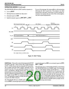
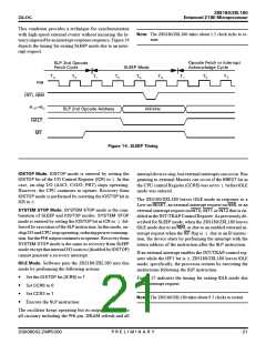
This condition provides a technique for synchronization
with high-speed external events without incurring the la-
tencyimposedbyaninterrupt-responsesequence.Figure14
depicts the timing for exiting 5.''2 mode due to an inter-
rupt request.
0QVGꢅ The Z8S180/Z8L180 takes about 1.5 clock ticks to re-
start.
1REQFGꢅ(GVEJꢅQTꢅ+PVGTTWRV
#EMPQYNGFIGꢅ%[ENG
5.2ꢅꢂPFꢅ1REQFG
(GVEJꢅ%[ENG
5.''2ꢅ/QFG
6
6
6
6
6
6
6
6
6
2*+
+06Kꢇꢅ0/+
#
#
5.2ꢅꢂPFꢅ1REQFGꢅ#FFTGUU
(((((*
*#.6
/ꢄ
(KIWTG ꢁꢉꢆ 5.''2ꢄ6KOKPI
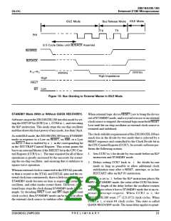
+15612ꢄ/QFGꢆꢄ+15612 mode is entered by setting the
+15612 bit of the I/O Control Register (+%4) to 1. In this
case, on-chip I/O (ASCI, CSI/O, PRT) stops operating.
However, the CPU continues to operate. Recovery from
+15612 mode is performed by resetting the +15612 bit in
+%4 to 0.
internal devices stop, but external interrupts can occur. Bus
granting to external Masters can occur if the $4'56 bit in
the CPU control Register (%%4ꢏ) was set to 1 before +&.'
mode was entered.
The Z8S180/Z8L180 leaves +&.' mode in response to a
Low on 4'5'6, an external interrupt request on 0/+, or an
external interrupt request on +06ꢀ, +06ꢄ or +06ꢂ that is en-
abled in the INT/TRAP Control Register. As previously de-
scribed for 5.''2 mode, when the Z8S180/Z8L180 leaves
+&.' mode due to an 0/+, or due to an enabled external in-
terrupt request when the +'( flag is 1 due to an '+ instruc-
tion, the device starts by performing the interrupt with the
return address of the instruction after the 5.2 instruction.
5;56'/ꢄ5612ꢄ/QFGꢆꢄ5;56'/ꢅ5612 mode is the com-
bination of 5.''2 and +15612 modes. 5;56'/ꢅ5612
mode is entered by setting the +15612 bit in +%4 to 1 fol-
lowed by execution of the 5.2 instruction. In this mode, on-
chipI/OandCPU stopoperating, reducingpower consump-
tion, but the 2*+output continuesto operate. Recoveryfrom
5;56'/ꢅ5612 mode is the same as recovery from 5.''2
mode exceptthat internal I/Osources(disabledby+15612)
cannot generate a recovery interrupt.
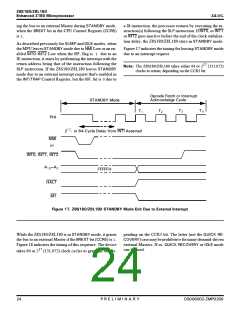
If an external interrupt enables the INT/TRAP control reg-
ister while the +'(ꢄ bit isꢅ0, Z8S180/Z8L180 leaves +&.'
mode; specifically, the processor restarts by executing the
instructions following the 5.2 instruction.
+&.'ꢄ/QFGꢆꢄSoftware puts the Z8S180/Z8L180 into this
mode by performing the following actions:
Set the +15612 bit (+%4ꢏ) to ꢄ
Set %%4ꢁ to ꢀ
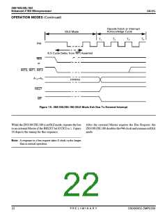
Figure 15 indicates the timing for exiting +&.' mode due
to an interrupt request.
Set %%4ꢍ to ꢄ
0QVGꢅ The Z8S180/Z8L180 takes about 9.5 clocks to restart.
Execute the 5.2 instruction
The oscillator keeps operating but its output is blocked to
all circuitry including the 2*+ pin. DRAM refresh and all
&5ꢀꢀꢁꢀꢀꢂꢃ</2ꢀꢂꢀꢀ
2ꢅ4ꢅ'ꢅ.ꢅ+ꢅ/ꢅ+ꢅ0ꢅ#ꢅ4ꢅ;
ꢂꢄ

 ZILOG [ ZILOG, INC. ]