eZ80L92 MCU
Product Specification
178
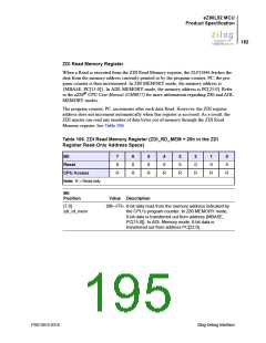
Bit
Position
Value Description
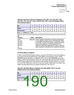
[7:0]
zdi_wr_mem
00h–FFh The 8-bit data that is transferred to the ZDI slave
following a Write to this address is written to the address
indicated by the current program counter. The program
counter is incremented following each 8 bits of data. In
Z80 MEMORY mode, ({MBASE, PC[15:0]}) ← 8 bits of
transferred data. In ADL MEMORY mode, (PC[23:0]) ←
8 bits of transferred data.
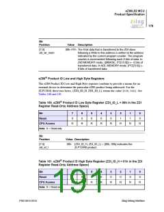
eZ80® Product ID Low and High Byte Registers
The eZ80 Product ID Low and High Byte registers combine to provide a means for an
external device to determine the particular eZ80 product being addressed. For the
ZLP12840, these two bytes, {ZDI_ID_H, ZDI_ID_L} return the value {00h, 06h}. See
Tables 100 and 101.
Table 100. eZ80® Product ID Low Byte Register (ZDI_ID_L = 00h in the ZDI
Register Read-Only Address Space)
Bit
7
0
6
0
5
0
4
0
3
0
2
1
1
1
0
0
Reset
CPU Access
Note: R = Read-only.
R
R
R
R
R
R
R
R
Bit
Position
Value Description
[7:0]
zdi_id_l
06h {ZDI_ID_H, ZDI_ID_L} = {00h, 06h} indicates the
ZLP12840 product.
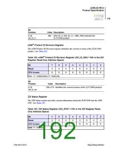
Table 101. eZ80® Product ID High Byte Register (ZDI_ID_H = 01h in the ZDI
Register Read-Only Address Space)
Bit
7
0
6
0
5
0
4
0
3
0
2
0
1
0
0
0
Reset
CPU Access
Note: R = Read-only.
R
R
R
R
R
R
R
R
PS013015-0316
Zilog Debug Interface

 ZILOG [ ZILOG, INC. ]