eZ80L92 MCU
Product Specification
154
accessed in SLAVE mode, the I2C completes the data transfer in SLAVE mode and then
enters MASTER mode when the bus is released. The STA bit is automatically cleared after
a START condition is set. Writing a 0 to this bit produces no effect.
If the Master Mode Stop bit (STP) is set to 1 in MASTER mode, a STOP condition is
transmitted on the I2C bus. If the STP bit is set to 1 in slave move, the I2C module operates
as if a STOP condition is received, but no STOP condition is transmitted. If both STA and
STP bits are set, the I2C block first transmits the STOP condition (if in MASTER mode)
and then transmit the START condition. The STP bit is cleared automatically. Writing a 0
to this bit produces no effect.
The I2C Interrupt Flag (IFLG) is set to 1 automatically when any of 30 of the possible 31
I2C states is entered. The only state that does not set the IFLG bit is state F8h. If IFLG is
set to 1 and the IEN bit is also set, an interrupt is generated. When IFLG is set by the I2C,
the Low period of the I2C bus clock line is stretched and the data transfer is suspended.
When a 0 is written to IFLG, the interrupt is cleared and the I2C clock line is released.
When the I2C Acknowledge bit (AAK) is set to 1, an Acknowledge is sent during the
acknowledge clock pulse on the I2C bus if:
•
•
•
Either the whole of a 7-bit slave address or the first or second byte of a 10-bit slave ad-
dress is received
The general call address is received and the General Call Enable bit in I2C_SAR is set
to 1
A data byte is received while in MASTER or SLAVE modes
When AAK is cleared to 0, a NACK is sent when a data byte is received in MASTER or
SLAVE mode. If AAK is cleared to 0 in the Slave Transmitter mode, the byte in the
I2C_DR register is assumed to be the final byte. After this byte is transmitted, the I2C
block enter states C8h, then returns to the idle state. The I2C module does not respond to
its slave address unless AAK is set. See Table 84.
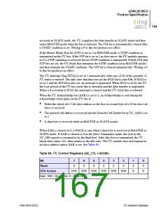
Table 84. I2C Control Registers (I2C_CTL = 00CBh)
Bit
7
0
6
0
5
0
4
0
3
0
2
0
1
0
0
0
Reset
CPU Access
R/W
R/W
R/W
R/W
R/W
R/W
R
R
Note: R/W = Read/Write; R = Read Only.
PS013015-0316
I2C Serial I/O Interface

 ZILOG [ ZILOG, INC. ]