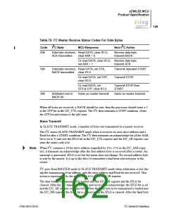
eZ80L92 MCU
Product Specification
153
Bit
Position
Value
Description
[7:0]
00h–FFh Least significant 8 bits of the 10-bit extended slave address.
SLAX
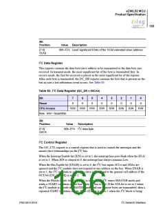
I2C Data Register
This register contains the data byte/slave address to be transmitted or the data byte just
received. In transmit mode, the most significant bit of the byte is transmitted first. In
receive mode, the first bit received is placed in the most significant bit of the register.
After each byte is transmitted, the I2C_DR register contains the byte that is present on the
bus in case a lost arbitration event occurs. See Table 83.
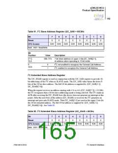
Table 83. I2C Data Register (I2C_DR = 00CAh)
Bit
7
0
6
0
5
0
4
0
3
0
2
0
1
0
0
0
Reset
CPU Access
Note: R/W = Read/Write.
R/W
R/W
R/W
R/W
R/W
R/W
R/W
R/W
Bit
Position
Value
Description
2
[7:0]
00h–FFh I C data byte.
DATA
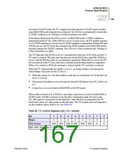
I2C Control Register
The I2C_CTL register is a control register that is used to control the interrupts and the
master slave relationships on the I2C bus.
When the Interrupt Enable bit (IEN) is set to 1, the interrupt line goes High when the IFLG
is set to 1. When IEN is cleared to 0, the interrupt line always remains Low.
When the Bus Enable bit (ENAB) is set to 0, the I2C bus inputs SCLx and SDAx are
ignored and the I2C module does not respond to any address on the bus. When ENAB is
set to 1, the I2C responds to calls to its slave address and to the general call address if the
GCE bit (I2C_SAR[0]) is set to 1.
When the Master Mode Start bit (STA) is set to 1, the I2C enters MASTER mode and
sends a START condition on the bus when the bus is free. If the STA bit is set to 1 when
the I2C module is already in MASTER mode and one or more bytes are transmitted, then a
repeated START condition is sent. If the STA bit is set to 1 when the I2C block is being
PS013015-0316
I2C Serial I/O Interface

 ZILOG [ ZILOG, INC. ]