eZ80L92 MCU
Product Specification
152
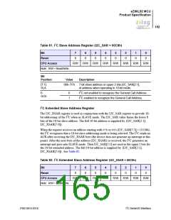
Table 81. I2C Slave Address Register (I2C_SAR = 00C8h)
Bit
7
0
6
0
5
0
4
0
3
0
2
0
1
0
0
0
Reset
CPU Access
Note: R/W = Read/Write.
R/W
R/W
R/W
R/W
R/W
R/W
R/W
R/W
Bit
Position
Value
00h–7Fh
Description
[7:1]
SLA
7-bit slave address or upper 2 bits,I2C_SAR[2:1],
of address when operating in 10-bit mode.
2
0
GCE
0
1
I C not enabled to recognize the General Call Address.
2
I C enabled to recognize the General Call Address.
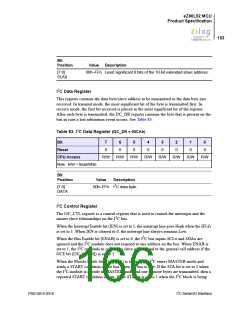
I2C Extended Slave Address Register
The I2C_XSAR register is used in conjunction with the I2C_SAR register to provide 10-
bit addressing of the I2C when in SLAVE mode. The I2C_SAR value forms the lower 8
bits of the 10-bit slave address. The full 10-bit address is supplied by {I2C_SAR[2:1],
I2C_XSAR[7:0]}.
When the register receives an address starting with F7h to F0h (I2C_SAR[7:3] = 11110b),
the I2C recognizes that a 10-bit slave addressing mode is being selected. The I2C sends an
ACK after receiving the I2C_XSAR byte (the device does not generate an interrupt at this
point). After the next byte of the address (I2C_XSAR) is received, the I2C generates an
interrupt and goes into SLAVE mode. Then I2C_SAR[2:1] are used as the upper 2 bits for
the 10-bit extended address. The full 10-bit address is supplied by {I2C_SAR[2:1],
I2C_XSAR[7:0]}. See Table 82.
Table 82. I2C Extended Slave Address Register (I2C_XSAR = 00C9h)
Bit
7
0
6
0
5
0
4
0
3
0
2
0
1
0
0
0
Reset
CPU Access
Note: R/W = Read/Write.
R/W
R/W
R/W
R/W
R/W
R/W
R/W
R/W
PS013015-0316
I2C Serial I/O Interface

 ZILOG [ ZILOG, INC. ]