eZ80L92 MCU
Product Specification
158
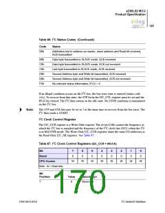
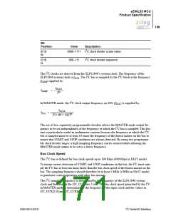
Bit
Position
Value
Description
2
[6:3]
M
0000–1111
I C clock divider scalar value.
2
[2:0]
N
000–111
I C clock divider exponent.
The I2C clocks are derived from the ZLP12840’s system clock. The frequency of the
ZLP12840 system clock is fSCK. The I2C bus is sampled by the I2C block at the frequency
fSAMP supplied by:
f
SCLK
f
=
SAMP
N
2
In MASTER mode, the I2C clock output frequency on SCL (fSCL) is supplied by:
f
SCLK
f
=
SCL
N
10 • (M + 1)(2)
The use of two separately-programmable dividers allows the MASTER mode output fre-
quency to be set independently of the frequency at which the I2C bus is sampled. This fea-
ture is particularly useful in multimaster systems because the frequency at which the I2C
bus is sampled must be at least 10 times the frequency of the fastest master on the bus to
ensure that START and STOP conditions are always detected. By using two programma-
ble clock divider stages, a high sampling frequency can be ensured while allowing the
MASTER mode output to be set to a lower frequency.
Bus Clock Speed
The I2C bus is defined for bus clock speeds up to 100 Kbps (400 Kbps in FAST mode).
To ensure correct detection of START and STOP conditions on the bus, the I2C must sam-
ple the I2C bus at least ten times faster than the bus clock speed of the fastest master on the
bus. The sampling frequency should therefore be at least 1 MHz (4 MHz in FAST mode)
to guarantee correct operation with other bus masters.
The I2C sampling frequency is determined by the frequency of the ZLP12840 system
clock and the value in the I2C_CCR bits 2 to 0. The bus clock speed generated by the I2C
in MASTER mode is determined by the frequency of the input clock and the values in
I2C_CCR[2:0] and I2C_CCR[6:3].
PS013015-0316
I2C Serial I/O Interface

 ZILOG [ ZILOG, INC. ]