eZ80L92 MCU
Product Specification
126
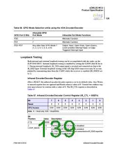
Table 66. GPIO Mode Selection while using the IrDA Encoder/Decoder
Allowable GPIO
Port Mode
GPIO Port D Bits
PD0
Allowable Port Mode Functions
Alternate Function
7
7
PD1
Alternate Function
PD2–PD7
Any other than GPIO Mode 7
(1, 2, 3, 4, 5, 6, 8, or 9)
Output, Input, Open-Drain, Open-Source,
Level-sensitive Interrupt Input, or Edge-
Triggered Interrupt Input
Loopback Testing
Both internal and external loopback testing can be accomplished with the endec on the
ZLP12840 MCU. Internal loopback testing is enabled by setting the LOOP_BACK bit to
1. During internal loopback, IR_TXD output signal is inverted and connected on-chip to the
IR_RXD input. External loopback testing of the off-chip IrDA transceiver may be accom-
plished by transmitting data from the UART while the receiver is enabled (IR_RXEN set
to 1).
Infrared Encoder/Decoder Register
After a RESET, the infrared encoder/decoder register is set to its default value. Any Writes
to unused register bits are ignored and Reads return a value of 0. Unused bits within a reg-
ister must always be written with a value of 0. The IR_CTL register is described in
Table 67.
Table 67. Infrared Encoder/Decoder Control Register (IR_CTL = 00BFh)
Bit
7
0
6
0
5
0
4
0
3
0
2
0
1
0
0
0
Reset
CPU Access
R/W
R/W
R/W
R/W
R/W
R/W
R/W
R/W
Note: R = Read only; R/W = Read/Write.
Bit
Position
Value Description
[7:3]
000000 Reserved.
2
0
1
Internal LOOP BACK mode is disabled.
Internal LOOP BACK mode is enabled.
LOOP_BACK
IR_TXD output is inverted and connected to IR_RXD input for
internal loop back testing.
PS013015-0316
Infrared Encoder/Decoder

 ZILOG [ ZILOG, INC. ]