MVTX2801
Data Sheet
Bit [7:0]:
•
(Default 00)
Content will send out by LED serial logic
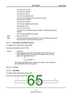
10.7.14 LEDUSER1
2
I C Address h0BC, Serial Interface Address:h60D
2
Accessed by serial interface and I C (R/W)
7
0
LED USER1
Bit [7:0]:
•
(Default 00)
Content will send out by LED serial logic
10.7.15 LEDUSER2/LEDSIG2
2
I C Address h0BD, Serial Interface Address:h60E
2
Accessed by serial interface and I C (R/W)
In serial mode:
7
0
LED USER2
Bit [7:0]:
•
(Default 00)
Content will be sent out by LED serial shift logic
In parallel mode: this register is used for programming the LED pin - led_byteout_[2]
7
4
3
0
SP0
COL
FDX
SP1
SP0
COL
FDX
SP1
Bit [3:0]:
Bit [7:4]
(Default 4'H0)
Signal polarity:
0: not invert polarity (high true)
1: invert polarity
(Default 4'H8)
Signal Select:
0: not select
1: select the corresponding bit
When bits get selected, the led_byteout_[2] = AND (all selected bits)
66
Zarlink Semiconductor Inc.

 ZARLINK [ ZARLINK SEMICONDUCTOR INC ]