MVTX2801
Data Sheet
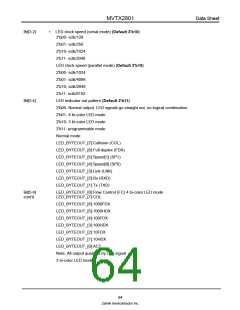
LED_BYTEOUT_[7]:COL
LED_BYTEOUT_[6]:LNK
LED_BYTEOUT_[5]:FC
LED_BYTEOUT_[4]:SPD1000
LED_BYTEOUT_[3]:SPD100 LED_BYTEOUT_[2]:FDX
LED_BYTEOUT_[1]:HDX
LED_BYTEOUT_[0]:ACT
Note: All output qualified by Link signal
Programmable mode:
LED_BYTEOUT_[7]:Link
LED_BYTEOUT_[6:0]:Defined by the LEDSIG6 ~ LEDSIG0 programmable
registers.
Note: All output qualified by Link signal
Reserved. Must be '0'
Bit[6]:
Bit[7]:
•
•
Enable internal loop back. When this bit is set to '1' all ports work in internal
loop back mode. For normal operation must be '0'.
10.7.11 CHECKSUM - EEPROM Checksum
2
I C Address h0C5, Serial Interface Address:h60B
2
Accessed by serial interface and I C (R/W)
Bit [7:0]:
•
•
(Default 00)
Before requesting that the MVTX2801 updates the EEPROM device, the
correct checksum needs to be calculated and written into this checksum
register. The checksum formula is:
FF
2
Σ
i = 0
i C register = 0
After booting cycle the MVTX2801 calculates the checksum. If the checksum is
not zeroed the MVTX2801 does not start.
10.7.12 LED User
10.7.13 LEDUSER0
2
I C Address h0BB, Serial Interface Address:h60C
2
Accessed by serial interface and I C (R/W)
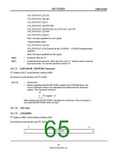
7
0
LED USER0
65
Zarlink Semiconductor Inc.

 ZARLINK [ ZARLINK SEMICONDUCTOR INC ]