MVTX2801
Data Sheet
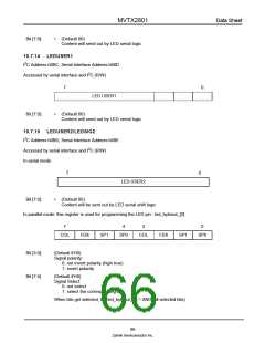
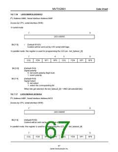
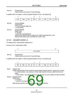
Bit [7:0]
(Default 8'H40)
Content will be sent out by LED serial shift logic.
In parallel mode: this register is used for programming the LED pin - led_byteout_[6]
7
4
3
0
COL
FDX
SP1
SP0
COL
FDX
SP1
SP0
Bit [3:0]
Bit [7:4]
(Default 4'B0000)
Signal polarity:
0: not invert polarity (high true)
1: invert polarity
(Default 4'b0100)
Signal Select:
0: not select
1: select the corresponding bit
When bits get selected, the led_byteout_[6] = AND (all selected bits), or the
polarity of led_byteout_[6] is controlled by LEDSIG1_0[3]
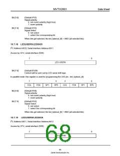
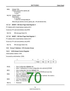
10.7.20 LEDUSER7/LEDSIG1_0
2
I C Address:h0C2, Serial Interface Address:h613
Access by CPU, serial interface (R/W)
7
0
LED USER7
Bit [7:0]
(Default 8'H61)
Content will be sent out by LED serial shift logic.
In parallel mode: this register is used for programming the LED pin - led_byteout_[2]
7
4
3
0
GP
RX
TX
FC
P6
RX
TX
FC
Bit [7]
(Default 1'B0)
Global output polarity: this bit controls the output polarity of all led_byteout_ and led_port_sel pins.
0: no invert polarity - (led_byteout_[7:0] are high activated, led_port_sel[9:0] are low acti-
vated)
1: invert polarity - (led_byteout_[7:0] are low activated, led_port_sel[9:0] are high activated)
Bit [6:4] (Default 3'B110)
Signal Select
0: not select
1: select the corresponding bit
When bits get selected, the led_byteout_[6] = OR (all selected bits)
69
Zarlink Semiconductor Inc.

 ZARLINK [ ZARLINK SEMICONDUCTOR INC ]