MVTX2801
Data Sheet
Bit[3:2]
•
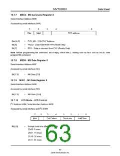
LED clock speed (serial mode) (Default 2'b10)
2'b00- sclk/128
2'b01- sclk/256
2'b10- sclk/1024
2'b11- sclk/2048
LED clock speed (parallel mode) (Default 2'b10)
2'b00- sclk/1024
2'b01- sclk/4096
2'b10- sclk/2048
2'b11- sclk/8192
Bit[5:4]
LED indicator out pattern (Default 2'b11)
2'b00- Normal output, LED signals go straight out, no logical combination
2'b01- 4 bi-color LED mode
2'b10- 3 bi-color LED mode
2'b11- programmable mode
Normal mode:
LED_BYTEOUT_[7]:Collision (COL)
LED_BYTEOUT_[6]:Full duplex (FDX)
LED_BYTEOUT_[5]:Speed[1] (SP1)
LED_BYTEOUT_[4]:Speed[0] (SP0)
LED_BYTEOUT_[3]:Link (LNK)
LED_BYTEOUT_[2]:Rx (RXD)
LED_BYTEOUT_[1]:Tx (TXD)
Bit[5:4]
cont’d
LED_BYTEOUT_[0]:Flow Control (FC) 4 bi-color LED mode
LED_BYTEOUT_[7]:COL
LED_BYTEOUT_[6]:1000FDX
LED_BYTEOUT_[5]:1000HDX
LED_BYTEOUT_[4]:100FDX
LED_BYTEOUT_[3]:100HDX
LED_BYTEOUT_[2]:10FDX
LED_BYTEOUT_[1]:10HDX
LED_BYTEOUT_[0]:ACT
Note: All output qualified by Link signal
3 bi-color LED mode:
64
Zarlink Semiconductor Inc.

 ZARLINK [ ZARLINK SEMICONDUCTOR INC ]