MA28138
3. CTU DATA TRANSFER TO OR FROM ONE RBI
If desired, the talker’s PA can be set to its TA or be disabled
for added security. Groups can be reconfigured by the CTU so
that, for example, one RBI can belong to more than one group.
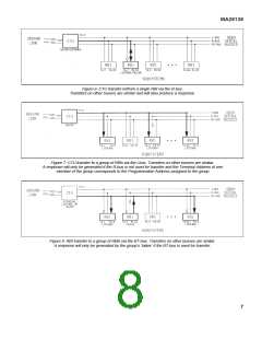
An example BT-bus transfer from one RBI to the remainder of
its group is shown in Figure 8.
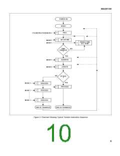
Depending upon the selected transfer bus, the CTU sends
either one or a series of Mode 7 ‘Proceed’ commands to one
RBl’s unique hard-wired Terminal Address. I- or R-bus
transfers will require one ‘Proceed’ command to be sent per
data word transferred; BT-bus transfers require only one
‘Proceed’ per data block. Data for ‘Input from l-bus’ transfers
must be embedded in bits 15-30 of the Interrogation as
immediate data; data for R- or BT-bus transfers must be driven
onto or read from the selected bus after the usual ‘3 slot delay’
by the CTU. I- and R-bus data transfer is rigidly controlled by
the CTU on a ‘word-by-word’ basis; BT-bus transfer is merely
initiated by the CTU and then proceeds autonomously. The
selected RBI responds as per Table 1 and can be monitored
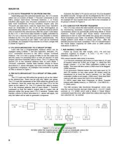
accordingly. An example R-bus transfer to or from a single RBI
is shown in Figure 6.
6. CTU CHECKS FOR PROPER TRANSFER
The CTU may check the data transfer process as it occurs
by monitoring available response(s) to the ‘Proceed’
command(s) and/or by periodically performing Mode 0 ‘Read
Address’, ‘Read Length’ and ‘Read Status’ instructions
addressed in turn to each RBI within the group and checking
those responses (see Table 1 for details). Alternatively, it may
simply perform such Mode 0 checks just once - after the
transfer process has been completed. The CTU should inspect
the ‘Read Status’ response for DMA error or DMA overrun
indications in bits 4-6.
4. CTU DATA BROADCAST TO A GROUP OF RBIs
Each RBI has a Programmable Address which can be
changed using a Mode 1 ‘Set Bus Selection, direction, PA,
UCC’ command directed to the RBl’s unique Terminal
Address. The CTU sets a group of RBls to use the same bus
and the same PA (ensuring that it is both an unused TA and
unique) and then transmits data to them. The CTU places the
chosen PA in the terminal address field of each Mode 7
‘Proceed’ command. Similar data transfer criteria to those
described in 2. above will apply, but none of the RBls are able
to generate a response. An example l-bus transfer to a group
of RBls is shown in Figure 7.
7. RBI ANOMALY DETECTION
Power up resets the RBI length, UCC, PA and bus
selection registers to length = 0, UCC = 0, PA = 63 (=
disabled), status bits 4 - 6 = 111.
RBI cannot transfer data when it receives:
1) a Proceed command (all modes) or input data (II, IR and
IB modes) when the DONE pin is high, i.e. when the RBI
length counter = 0 or the DMA controller’s buffer is not
empty. This error will also cause a DMA error to be flagged.
(DMA overrun).
2) no processor DMAKn before the next data word (II, IR
and OR modes) or two data words (IB mode) must be
transferred to or from the user’s memory, i.e. the DMA
controller’s buffer is not empty. (DMA error). Note that DMA
overrun will also cause this error to be indicated.
3) OBDH input data from Response or Block Transfer
busses with validity error(s), i.e. RRRVAL = 0 or RBRVAL =
0. (DMA error).
5. RBI DATA BROADCAST TO A GROUP OF RBIs (AND
CTU)
The CTU sets one RBI within the group to act as the ‘talker’
to the desired bus. There can be only one ‘talker’ per group.
The CTU sets the remainder of the RBls within the group to act
as ‘listeners’ from the same bus and sets their PA to be the
same as the talker’s TA. The CTU places the talker’s unique
TA in the terminal address field of each Mode 7 ‘Proceed’
command so that the talker’s output data is copied into all
listeners within the group (and CTU if needed). Similar data
transfer criteria to those described in 2. above will apply, but
only the talker will be able to generate a response.
The RBI remains fully functional throughout: errors only
stop the current transfer and jam status bits 4 - 6 to 011 (DMA
overrun) or 111 (DMA error) until a Mode 0 ‘Read Status’
command reads the error, after which the status bits report the
bus selection etc. as normal.
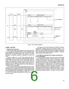
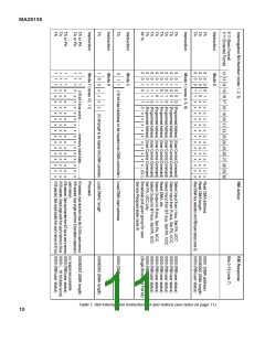
Figure 5: CTU set up of an individual RBI.
All RBls within the required group must be set up individually unless the
Extended Addressing mode is enabled (EXTAEN = 1)
6

 ZARLINK [ ZARLINK SEMICONDUCTOR INC ]