MA28138
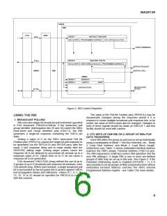
USER
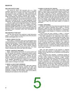
RBI
CTU
DBU
MODE 1
INSTRUCT RBI/USER
I-Bus
BUS & DIR'N PROGRAMMED ADDRESS UCC (UCC(0:5) & UCCS)
USER COMMANDS
MODE 0
RBI/USER STATUS
R-Bus
BUS & DIR'N USER (SREQ & BIL(0:5)) PROGRAMMED ADDRESS
Z
SERVICE REQUEST
USER BI-LEVEL
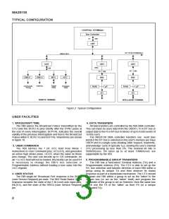
OBDH
DBI
DMAC
MODE 3
MODE 4
ADDRESS
LENGTH
ZERO
MULTIPLEXED
µP-BUS
DATA BUFFERS
BT-Bus
Figure 4: RBI Control Registers
The value of the Poll Bit Position pins (PBP(0:4)) may be
dynamically changed during the response period if it is
required to create multiple broadcast poll response bits; to be
useful, the value of SREQ must also be changed. Changes to
both of these signals should be made as RIRCLK ↑ and this
facility should be used with caution.
USING THE RBI
1. BROADCAST POLLING
RBI executes single-bit broadcast poll instruction specified
in ESA document THB/APo/1906/av. If the instruction poll
group identifier (interrogation bits 29 and 30) match the RBl’s
hard-wired poll Group Identifier pins (Gl(0:1)), the RBI
generates a single-bit response containing the SREQ pin
state.
2. CTU SETS UP ONE RBI OR A GROUP OF RBIs FOR
DATA TRANSFERS
Setting a value of 0 on the RBl’s hard-wired Poll Bit
Position pins (PBP(0:4)) causes the single-bit poll response to
be generated (on the RRTDATA and RRTEN pins) after the
usual ‘3 slot’ response delay and to begin shortly after the
RIRSYNC falling edge. Setting larger values cause the
response bit to be delayed by successive bit periods up to a
maximum value of 23. Values from 24 to 31 do not cause a
response bit to be generated.
ESA document THB/1229/LJ/mvg defines the use of up to
4 groups of up to 8 broadcast poll response bit windows, each
3 bit periods long. Within each window, a single broadcast poll
bit is surrounded by two bit guard bits to protect against OBDH
bus propagation delays and reflections. Values of 1, 4, 7, 10,
13, 16, 19 or 22 should be specified for PBP(0:4) to comply
with this scheme.
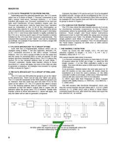
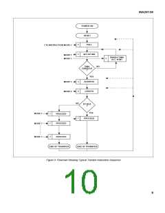
Each RBI within the group (or just one) is set up individually
using a combination of Mode 1 ‘Set Bus Selection, etc.’, Mode
3 ‘Load Start Address’ and Mode 4 ‘Load Block Length’
instructions (see Table 1) whose embedded terminal address
matches the RBl’s unique Terminal Address (TA(0:5)) pins.
The RBI response(s) confirm(s) correct RBI operation and the
new RBI setting(s). A single RBI or one or more pre-defined
groups of RBls may be set up in this way. See Figure 5. If the
Extended Addressing mode is Enabled (EXTAEN = 1), it is
also possible to set up groups of RBls using instructions whose
embedded terminal address matches the RBl’s internal
Programmed Address register - see Table 2 for more details.
5

 ZARLINK [ ZARLINK SEMICONDUCTOR INC ]