MA28138
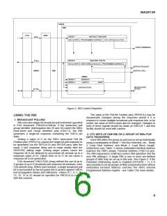
TYPICAL CONFIGURATION
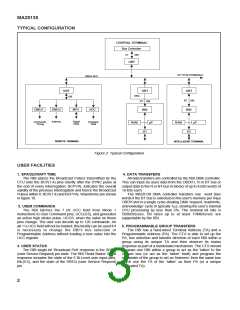
CENTRAL TERMINAL
Bus Controller
CT
DBI
OBT
UP TO 60 TERMINALS
OBDH BUS
OBT
OBT
OBT
RT DBI
RBI
DBU
IUB
RT DBI
DMUX
DMUX
Address
MPX
ADC
RBI
Digital
Data
Commands
Timing
Analogue
Data
RAM
µP
RAM
µP
I/O
I/O
REMOTE TERMINAL
INTELLIGENT TERMINAL
Figure 2: Typical Configuration
USER FACILITIES
1. SPACECRAFT TIME
4. DATA TRANSFERS
The RBI places the BroadCast Pulses transmitted by the
CTU onto the BCP(1:4) pins shortly after the SYNC pulse at
the end of every Interrogation. BCPVAL indicates the overall
validity of the previous Interrogation and hence the BroadCast
Pulses within it. BCP(1:4) and BCPVAL Waveforms are shown
in figure 10.
All data transfers are controlled by the RBI DMA controller.
This can input (to user) data from the OBDH l, R or BT bus or
output data to the R or BT bus in blocks of up to 4,095 words of
16-bits each.
The MA28138 DMA controller transfers one word (two
words if the BT bus is selected) to the user's memory per 64µs
OBDH slot in a single cycle-stealing DMA ‘request, read/write,
acknowledge’ cycle in typically 1µs, slowing the user’s internal
CPU processing by less than 2%. The nominal bit rate is
500kBits/sec. Bit rates up to at least 10Mbits/sec are
supportable by the RBI.
2. USER COMMANDS
The RBI latches the 7 bit UCC field from Mode 1
instructions to User Command pins, UCC(0:6), and generates
an active high strobe pulse, UCCS, when the value on these
pins change. The user can decode up to 126 commands. An
all-‘1’s UCC field will not be loaded; this facility can be used if it
is necessary to change the RBI's bus selection or
Programmable Address without loading a new value into the
UCC register.
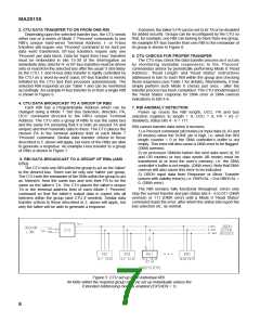
5. PROGRAMMABLE GROUP TRANSFERS
The RBI has a hard-wired Terminal Address (TA) and a
Programmable Address (PA). The CTU is able to set up the
PA, bus selection and transfer direction of each RBI within a
group using its unique TA and then observe its status
response as part of a handshake mechanism. The CTU should
program one RBI within a group to act as the ‘talker’ to the
chosen bus (or act as the ‘talker’ itself) and program the
remainder of the group to act as ‘listeners’ from the same bus
which use the TA of the ‘talker’ as their PA (or a unique
dedicated TA).
3. USER STATUS
The RBI single bit ‘Broadcast Poll’ response is the SREQ
(user Service Request) pin state. The RBI ‘Read Status’ 21-bit
response includes the state of the 6 Bi-Level user input pins,
BIL(0:5), and the state of the SREQ (user Service Request)
pin.
2

 ZARLINK [ ZARLINK SEMICONDUCTOR INC ]