Le77D11
Data Sheet
PRODUCT DESCRIPTION
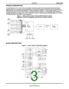
The dual channel Le77D11 VoSLIC device uses reliable, dielectrically isolated, fully complementary bipolar technology to
implement BORSCHT functions for short loop applications. Internal power dissipation is minimized by two independent line
voltage tracking, buck-boost switching regulators. Two power supplies are required: 3.3 V and a positive supply (VSW). A TTL-
level clock driven by the Le78D11 VoSLAC device is required for switcher operation. Six programmable states control loop
signaling, transmission, and ringing. The Le77D11 Dual VoSLIC device DC current limit (ISC) is programmable from 15 to 45 mA.
The following diagram demonstrates a typical application.
Figure 1. Typical Le77D11 VoSLIC™ Device/Le78D11 VoSLAC™ device
Application in an 8-Port Integrated Access Device in Customer Premises
Din
1
Le77D11
Le78D11
Dout
PCM I/F
Le77D11
Le77D11
Le77D11
Le78D11
Le78D11
Le78D11
DSP
Network
Processor
Loop/Cable
WLL
DSLAM/
HEADEND
MODEM
DCLK/CS
Din
Dout
Data Interfaces
8
Ethernet USB HomePNA
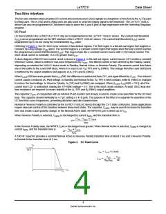
BLOCK DESCRIPTIONS
Figure 2. Le77D11 VoSLIC™ Device Block Diagram
F1
Fault
NPRFILT1
VIN1
VOUT1
VHP1
CFILT1
LPF1
Detection
Signal
Transmission
A1 (TIP)
2-Wire
Interface
B1 (RING)
Signal
Conditioning
IMT1
RDC1
VREG1
SD1
ILS1
CHS1
Switcher
Controller
C11
C21
C31
Control
Logic
VSW
CHCLK
FSET
C12
C22
C32
Control
Logic
SD2
ILS2
CHS2
Switcher
Controller
VREG2
A
2 (TIP)
Signal
Conditioning
IMT2
RDC2
2-Wire
Interface
B2 (RING)
NPRFILT2
VIN2
VOUT2
VHP2
CFILT2
LPF2
Signal
Transmission
Fault
Detection
F2
BGND1
BGND2
AGND
VCC
VREF
3
Zarlink Semiconductor Inc.

 ZARLINK [ ZARLINK SEMICONDUCTOR INC ]