Le58083
Data Sheet
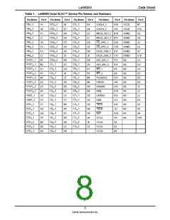
PIN DESCRIPTIONS
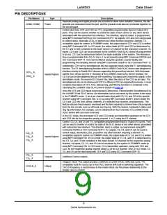
Pin Names
Type
Description
Separate analog and digital grounds are provided to allow noise isolation; however, the two
grounds are connected inside the part, and the grounds must also be connected together on
the circuit board.
AGND, DGND
Power
Control and Data. CD1 and CD2 are TTL compatible programmable Input or Output (I/O)
ports. They can be used to monitor or control the state of SLIC device or any other device
associated with the subscriber line interface. The direction, input or output, is programmed
using MPI Command 54/55h or GCI Command SOP 8. As outputs, CD1 and CD2 can be used
to control relays, illuminate LEDs, or perform any other function requiring a latched TTL
compatible signal for control. In PCM/MPI mode, the output state of CD1 and CD2 is written
using MPI Command 52h. In GCI mode, the output state of CD1 and CD2 is determined by
the C1 and C2 bits contained in the down stream C/I channel for the respective channel. As
inputs, CD1 and CD2 can be processed by the Le58083 Octal SLAC device (if programmed
to do so). CD1 can be debounced before it is made available to the system. The debounce
time is programmable from 0 to 15 ms in 1 ms increments using MPI Command C8/C9h and
GCI Command SOP 11. CD2 can be filtered using the up/down counter facility and
programming the sampling interval using MPI Command E8/E9h or GCI Command SOP 12.
Additionally, CD1 can be demultiplexed into two separate inputs using the E1 demultiplexing
function. The E1 demultiplexing function of the Le58083 Octal SLAC device was designed to
interface directly to Zarlink SLIC devices supporting the ground key function. With the proper
Zarlink SLIC device and the E1 function of the Le58083 Octal SLAC device enabled, the
CD1 bit can be demultiplexed into an Off-Hook/Ring Trip signal and Ground Key signal. In the
demultiplex mode, the second bit, Ground Key, takes the place of the CD2 as an input. The
demultiplexed bits can be debounced (CD1) or filtered (CD2) as explained previously. A more
complete description of CD1, CD2, debouncing, and filtering functions is contained in the
Operating the Le58083 Octal SLAC Device section on page 30.
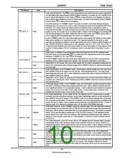
CD1 _X,
C
Inputs/Outputs
CD2 _X
C
Once the CD1 and CD2 inputs are processed (Debounced, Filtered and/or Demultiplexed) by
the Le58083 Octal SLAC device, the information can be accessed by the system in two ways
in the PCM/MPI mode: 1) on a per channel basis along with C3, C4, and C5 of the specific
channel using MPI Command 53h, or 2) by using MPI Command 4D/4Fh, which obtain the
CD1 and CD2 bits from all four channels, of a selected four-channel, simultaneously. This
feature reduces the processor overhead and the time required to retrieve time-critical signals
from the line circuits, such as off-hook and ring trip. With this feature, hookswitch status and
ring trip information, for example, can be obtained from four channels of a Le58083 Octal
SLAC device with one read command.
In the GCI mode, the processed CD1 and CD2 inputs are transmitted upstream on the CD1
and CD2 bits for the respective analog channel, 1 or 2, using the C/I channel.
Control. C3, C4, and C5 are TTL-compatible programmable Input or Output (I/O) ports. They
can be used to monitor or control the state of the SLIC device or any other device associated
with subscriber line interface. The direction, input or output, is programmed using MPI
Command 54/55h or GCI Command SOP 8. As outputs, C3, C4, and C5 can be used to
control relays, illuminate LEDs, or perform any other function requiring a latched TTL
compatible signal for control. In PCM/MPI mode, the output state of C3, C4, and C5 is written
using MPI Command 52h. In GCI mode, the output state of C3, C4, and C5 is determined by
the C3, C4, and C5 bits contained in the down stream C/I channel for the respective analog
channel. As inputs, C3, C4, and C5 can be accessed by the system in PCM/MPI mode by
using MPI Command 53h. In GCI mode, C3 is transmitted upstream, along with CD1 and
CD2, for the respective analog channel using C3 of the C/I channel. Also, in GCI mode, C3,
C4, and C5 can be read along with CD1 and CD2 using GCI Command SOP 10.
C3 _X,
C
C4 _X,
Inputs/Outputs
C
C5 _X
C
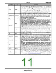
C6 _X,
C
Outputs
Output
Additional Control outputs.
C7 _X
C
Chopper Clock. This output provides a 256 kHz or a 292.57 kHz, 50% duty cycle, TTL-
compatible clock for use by up to four SLIC devices with built-in switching regulators. The
CHCLK frequency is synchronous to the master clock, but the phase relationship to the
master clock is random.
CHCLK_X
9
Zarlink Semiconductor Inc.

 ZARLINK [ ZARLINK SEMICONDUCTOR INC ]