GP2021
The TIC bit is set High at every TIC and is cleared by
reading this ACCUM_STATUS_B register. Its purpose is
to tell the microprocessor that new Measurement Data is
available. It is reset by a hardware master reset (NRESET
at low) but not by an MRB in RESET_CONTROL.
ACCUM_STATUS_C bits are sampled and latched on the
active edge of every ACCUM_INT signal, or they can be
sampled and latched on request by performing a write
operation to STATUS (as with ACCUM_STATUS A).
The CHx_EARLY_LATEB status bit indicates the code
type for the Accumulated Data on the Tracking arm of
channel CHx when that channel is in Dithering mode. A
high indicates an EARLYcode and a low indicates a LATE
code. Each individual bit is determined on the DUMP that
sets CHx_NEW_ACCUM_DATA to high for that channel.
In other modes the bit is of no use.
Provided that interrupts are enabled, the MEAS_INT bit is
set High at each TIC and 50ms before each TIC if the TIC
period is greater then 50ms), and is cleared by reading
this register. This bit can be used as a flag to the
microprocessor, to time software module swapping. It is
reset by a hardware master reset (NRESET at low), but
not by a software reset. CHx_MISSED_ACCUM status bit
indicates (when high) that there has been missed
Accumulated Data due to a new DUMP in CHx before the
previous data has been read. This bit is latched until the
associated CHx_ACCUM_RESET is written to. If any data
is missed due to the reading process being too slow this
must be allowed for in the software, such as by checking
the Navigation Message data bit transitions independently
of the sets of Accumulated Data reads. If too much data is
lost the system signal to noise ratio will be degraded. The
primary purpose of these bits is as a check on how well
the tracking routines are working - once the whole design
is complete these bits should not become set.
Note that the channel specific bits of this register will not
show their new value until after an active edge of
ACCUM_INT or a write to the STATUS register. Disabling
a channel will however, clear the bit immediately.
CHx_ACCUM_RESET (Write Address)
Bits 15 to 0: Not used.
These are write-only locations provided to allow resetting
of
the
status
bits
ACCUM_STATUS_A,
ACCUM_STATUS_B, and ACCUM_STATUS_C
associated with a given channel or all channels. When
these locations are written to, the data is irrelevant.
Note that the channel-specific bits of this register will not
show their new value until after an active edge of
ACCUM_INT or a write to the STATUS register. Disabling
a channel will however, clear the bit immediately.
CHx_CARRIER_CYCLE_COUNTER,
MULTI_CARRIER_CYCLE_COUNTER,
ALL _CARRIER_CYCLE_COUNTER
(Write Address)
Awrite to these registers only has effect when in test mode
(bit 3 of TEST_CONTROL set high). The value on the bus
is loaded into the lower 16 bits of the
CHx_CARRIER_CYCLE_COUNTER along with zeros into
the upper 4 bits.
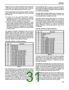
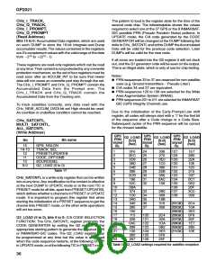
ACCUM_STATUS_C (Read address)
Bit
Bit name
15
14
13
12
11
10
9
8
7
6
5
Not used - low
Not used - low
Not used - low
Not used - low
CHx_CARRIER_CYCLE_HIGH,
CHx_CARRIER_CYCLE_LOW
(Read Address)
CH11_EARLY_LATEB
CH10_EARLY_LATEB
CH9_EARLY_LATEB
CH8_EARLY_LATEB
CH7_EARLY_LATEB
CH6_EARLY_LATEB
CH5_EARLY_LATEB
CH4_EARLY_LATEB
CH3_EARLY_LATEB
CH2_EARLY_LATEB
CH1_EARLY_LATEB
CH0_EARLY_LATEB
_HIGH bits 15 to 4: not used - low when read.
_HIGH bits 3 to 0: Carrier Cycle Count bits 19 to 16.
_LOW bits 15 to 0: Carrier Cycle Count bits 15 to 0.
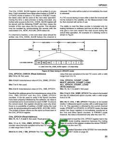
The Correlator tracking channel hardware allows for
measurement of integrated carrier phase through the
CHx_CARRIER_CYCLE_HIGH and _LOW and the
CHx_CARRIER_DCO_PHASE registers, which are part
of the Measurement Data sampled at every TIC. The
CHx_CARRIER_CYCLE_HIGH and _LOW registers
contain the 20- bit number of positive going zero crossings
of the Carrier DCO (4 bits are in _HIGH and 16 in _LOW).
4
3
2
1
0
Table 16
32

 ZARLINK [ ZARLINK SEMICONDUCTOR INC ]