GP2021
TYPICAL GPS RECEIVER
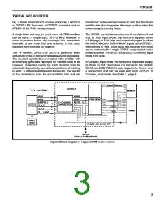
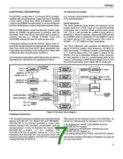
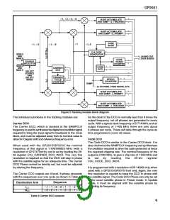
Fig. 3 shows a typical GPS receiver employing a GP2010
or GP2015 RF front end, a GP2021 correlator and an
ARM60 32-bit RISC microprocessor.
transferred to the microprocessor to give the broadcast
satellite data (the Navigation Message) and to control the
software signal tracking loops.
A single front end may be used, since all GPS satellites
use the same L1 frequency of 1575·42 MHz. However, in
order to achieve better sky coverage, it is sometimes
desirable to use more than one antenna. In this case,
separate front ends will be required.
The GP2021 can be interfaced to one of two styles of front
end. In Real_lnput mode, the front end supplies either
a 1-bit (sign) or 2-bit (sign and magnitude) signal to either
the SIGN0/MAG0 or SIGN1/MAG1 inputs of the GP2021.
Alternatively, in Real_lnput mode, two separate front ends
can be connected to a single GP2021 and selected under
software control. The GP2015 and GP2010 are Real_lnput
mode front ends.
The RF section, GP2010 or GP2015, performs down
conversion of the L1 signal for digital baseband processing.
The resultant signal is then correlated in the GP2021 with
an internally generated replica of the satellite code to be
received. Individual codes for each channel may be
selected independently to enable acquisition and tracking
of up to 12 different satellites simultaneously. The results
of the correlations form the accumulated data and are
In Complex_lnput mode, the front end is required to supply
In-phase (I) and Quadrature (Q) signals to the SIGN0/
MAG0 and SIGN1/MAG1 inputs respectively. Hence, only
a single front end can be used with each GP2021 in
Complex_lnput mode. See Table 3, page 6.
MEMORY CONTROL
GP2021
L1 ANTENNA
MEMORY
SIGN
WREN
PERIPHERAL
FUNCTIONS
MAG
READ
CONTROL
SAMPCLK
CLK_T
CLK_I
MICRO_CLK
12-CHANNEL
CORRELATOR
GP2010/
GP2015
DATA
ARM60
ADDR
PLL_LOCK
10MHz
TCXO
ACCUM_INT, MEAS_INT
TX/RX
SERIAL COMMS PORT
Figure 3 Block diagram of a typical ARM-based receiver
3

 ZARLINK [ ZARLINK SEMICONDUCTOR INC ]