R
Platform Flash In-System Programmable Configuration PROMS
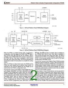
Table 5: XCFxxP Design Revision Data Security Options
Read/Verify
Inhibited
Program
Inhibited
Read Protect
Reset (default)
Write Protect
Reset (default)
Set
Erase Inhibited
Reset (default)
√
√
√
√
Set
Set
Reset (default)
Set
√
√
IEEE 1149.1 Boundary-Scan (JTAG)
The Platform Flash PROM family is IEEE Standard 1532
in-system programming compatible, and is fully compliant
with the IEEE Std. 1149.1 Boundary-Scan, also known as
JTAG, which is a subset of IEEE Std. 1532 Boundary-Scan.
A Test Access Port (TAP) and registers are provided to sup-
port all required boundary scan instructions, as well as
many of the optional instructions specified by IEEE Std.
1149.1. In addition, the JTAG interface is used to implement
in-system programming (ISP) to facilitate configuration, era-
sure, and verification operations on the Platform Flash
PROM device. Table 6 lists the required and optional
boundary-scan instructions supported in the Platform Flash
PROMs. Refer to the IEEE Std. 1149.1 specification for a
complete description of boundary-scan architecture and the
required and optional instructions.
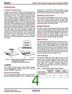
to a logic "0". The ISC Status field, IR[4], contains logic "1"
if the device is currently in In-System Configuration (ISC)
mode; otherwise, it contains logic "0". The Security field,
IR[3], contains logic "1" if the device has been programmed
with the security option turned on; otherwise, it contains
logic "0". IR[2] is unused, and is set to '0'. The remaining bits
IR[1:0] are set to '01' as defined by IEEE Std. 1149.1.
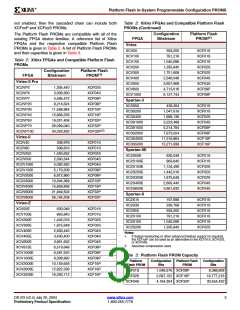
XCFxxP Instruction Register (16 bits wide)
The Instruction Register (IR) for the XCFxxP PROM is six-
teen bits wide and is connected between TDI and TDO dur-
ing an instruction scan sequence. The detailed composition
of the instruction capture pattern is illustrated in Figure 5.
The instruction capture pattern shifted out of the XCFxxP
device includes IR[15:0]. IR[15:9] are reserved bits and are
set to a logic "0". The ISC Error field, IR[8:7], contains a "10"
when an ISC operation is a success, otherwise a "01" when
an In-System Configuration (ISC) operation fails The
Erase/Program (ER/PROG) Error field, IR[6:5], contains a
"10" when an erase or program operation is a success, oth-
erwise a "01" when an erase or program operation fails. The
Erase/Program (ER/PROG) Status field, IR[4], contains a
logic "1" when the device is busy performing an erase or
programming operation, otherwise, it contains a logic "0".
The ISC Status field, IR[3], contains logic "1" if the device is
currently in In-System Configuration (ISC) mode; otherwise,
it contains logic "0". The DONE field, IR[2], contains logic
"1" if the sampled design revision has been successfully
programmed; otherwise, a logic "0" indicates incomplete
programming. The remaining bits IR[1:0] are set to '01' as
defined by IEEE Std. 1149.1.
Instruction Register
The Instruction Register (IR) for the Platform Flash PROM
is connected between TDI and TDO during an instruction
scan sequence. In preparation for an instruction scan
sequence, the instruction register is parallel loaded with a
fixed instruction capture pattern. This pattern is shifted out
onto TDO (LSB first), while an instruction is shifted into the
instruction register from TDI.
XCFxxS Instruction Register (8 bits wide)
The Instruction Register (IR) for the XCFxxS PROM is eight
bits wide and is connected between TDI and TDO during an
instruction scan sequence. The detailed composition of the
instruction capture pattern is illustrated in Figure 4.
The instruction capture pattern shifted out of the XCFxxS
device includes IR[7:0]. IR[7:5] are reserved bits and are set
DS123 (v2.4) July 20, 2004
Preliminary Product Specification
www.xilinx.com
1-800-255-7778
5

 XILINX [ XILINX, INC ]