Spartan-3E FPGA Family: Functional Description
The FPGA configuration sequence can also be initiated by
asserting PROG_B. Once released, the FPGA begins
clearing its internal configuration memory, and progresses
through the remainder of the configuration process.
Maximum Bitstream Size for Daisy-Chains
The maximum bitstream length supported by Spartan-3E
FPGAs in serial daisy-chains is 4,294,967,264 bits
(4 Gbits), roughly equivalent to a daisy-chain with 720
XC3S1600E FPGAs. This is a limit only for serial
daisy-chains where configuration data is passed via the
FPGA’s DOUT pin. There is no such limit for JTAG chains.
Configuration Sequence
For additional information including I/O behavior before and
during configuration, refer to the “Sequence of Events”
chapter in UG332.
The Spartan-3E configuration process is three-stage
process that begins after the FPGA powers on (a POR
event) or after the PROG_B input is asserted. Power-On
Reset (POR) occurs after the V
, V
, and the
CCINT
CCAUX
V
Bank 2 supplies reach their respective input threshold
CCO
levels. After either a POR or PROG_B event, the
three-stage configuration process begins.
1. The FPGA clears (initializes) the internal configuration
memory.
2. Configuration data is loaded into the internal memory.
3. The user-application is activated by a start-up process.
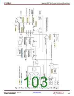
Figure 66 is a generalized block diagram of the Spartan-3E
configuration logic, showing the interaction of different
device inputs and Bitstream Generator (BitGen) options. A
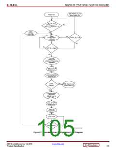
flow diagram for the configuration sequence of the Serial
and Parallel modes appears in Figure 66. Figure 67 shows
the Boundary-Scan or JTAG configuration sequence.
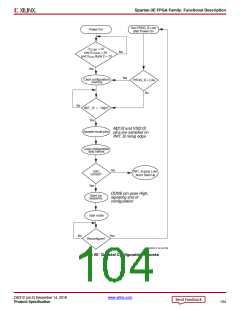
Initialization
Configuration automatically begins after power-on or after
asserting the FPGA PROG_B pin, unless delayed using the
FPGA’s INIT_B pin. The FPGA holds the open-drain INIT_B
signal Low while it clears its internal configuration memory.
Externally holding the INIT_B pin Low forces the
configuration sequencer to wait until INIT_B again goes
High.
The FPGA signals when the memory-clearing phase is
complete by releasing the open-drain INIT_B pin, allowing
the pin to go High via the external pull-up resistor to
VCCO_2.
Loading Configuration Data
After initialization, configuration data is written to the
FPGA’s internal memory. The FPGA holds the Global
Set/Reset (GSR) signal active throughout configuration,
holding all FPGA flip-flops in a reset state. The FPGA
signals when the entire configuration process completes by
releasing the DONE pin, allowing it to go High.
DS312 (v4.2) December 14, 2018
www.xilinx.com
Product Specification
102

 XILINX [ XILINX, INC ]