X1241 – Preliminary Information
Random Read
loaded address. This operation could be useful if the
master knows the next address it needs to read, but is
not ready for the data.
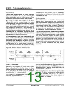
Random read operation allows the master to access
any memory location in the array. Prior to issuing the
Slave Address Byte with the R/W bit set to one, the
master must first perform a “dummy” write operation.
Sequential Read
Sequential reads can be initiated as either a current
address read or random address read. The first Data
Byte is transmitted as with the other modes; however,
the master now responds with an acknowledge, indicat-
ing it requires additional data. The device continues to
output data for each acknowledge received. The master
terminates the read operation by not responding with
an acknowledge and then issuing a stop condition.
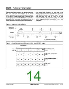
The master issues the start condition and the Slave
Address Byte, receives an acknowledge, then issues
the Word Address Bytes. After acknowledging receipts
of the Word Address Bytes, the master immediately
issues another start condition and the Slave Address
Byte with the R/W bit set to one. This is followed by an
acknowledge from the device and then by the eight bit
word. The master terminates the read operation by not
responding with an acknowledge and then issuing a
stop condition. Refer to Figure 11 for the address,
acknowledge, and data transfer sequence.
The data output is sequential, with the data from address
n followed by the data from address n + 1. The address
counter for read operations increments through all page
and column addresses, allowing the entire memory
contents to be serially read during one operation. At
the end of the address space the counter “rolls over” to
the start of the address space and the device continues
to output data for each acknowledge received. Refer to
Figure 12 for the acknowledge and data transfer
sequence.
In a similar operation, called “Set Current Address,” the
device sets the address if a stop is issued instead of the
second start shown in Figure 11. The X1241 then goes
into standby mode after the stop and all bus activity will
be ignored until a start is detected.This operation loads
the new address into the address counter. The next Cur-
rent Address Read operation will read from the newly
Figure 15. Random Address Read Sequence
S
S
S
t
o
p
t
a
r
Word
Address 0
Slave
Address
Slave
Address
Word
Address 1
t
a
r
Signals from
the Master
t
t
SDA Bus
1
1 1 1 0
0 0 0 0 0
1
1 1 1 1
A
C
K
A
C
K
A
C
K
A
C
K
Signals from
the Slave
Data
DEVICE ADDRESSING
The last bit of the Slave Address Byte defines the oper-
ation to be performed. When this R/W bit is a one, then
a read operation is selected. A zero selects a write
operation. Refer to Figure 12.
Following a start condition, the master must output a
Slave Address Byte. The first four bits of the Slave
Address Byte specify access to the EEPROM array or
to the CCR. Slave bits ‘1010’ access the EEPROM
array. Slave bits ‘1101’ access the CCR.
After loading the entire Slave Address Byte from the
SDA bus, the device compares the device identifier
and device select bits with ‘1010111’ or ‘1101111’.
Upon a correct compare, the device outputs an
acknowledge on the SDA line.
Bit 3 through Bit 1 of the slave byte specify the device
select bits.These are set to ‘111’.
Characteristics subject to change without notice. 13 of 22
REV 1.1.3 2/13/01
www.xicor.com

 XICOR [ XICOR INC. ]