X1241 – Preliminary Information
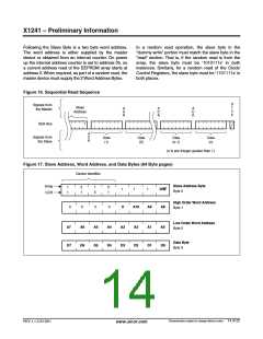
Following the Slave Byte is a two byte word address.
The word address is either supplied by the master
device or obtained from an internal counter. On power
up the internal address counter is set to address 0h, so
a current address read of the EEPROM array starts at
address 0. When required, as part of a random read, the
master device must supply the 2 Word Address Bytes.
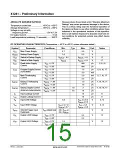
In a random read operation, the slave byte in the
“dummy write” portion must match the slave byte in the
“read” section. That is, if the random read is from the
array, the slave byte must be ‘1010111x’ in both
instances. Similarly, for a random read of the Clock/
Control Registers, the slave byte must be ‘1101111x’ in
both places.
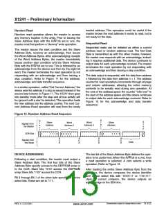
Figure 16. Sequential Read Sequence
S
Signals from
Slave
t
A
C
K
A
C
K
A
C
K
the Master
o
p
Address
SDA Bus
1
A
C
K
Signals from
the Slave
Data
(2)
Data
(n-1)
Data
(1)
Data
(n)
(n is any integer greater than 1)
Figure 17. Slave Address, Word Address, and Data Bytes (64 Byte pages)
Device Identifier
Slave Address Byte
Array
CCR
1
1
0
1
1
0
0
1
1
1
1
R/W
A8
Byte 0
High Order Word Address
0
0
0
0
0
A10
A9
Byte 1
Low Order Word Address
A7
D7
A6
D6
A5
D5
A4
D4
A3
D3
A2
D2
A1
D1
A0
D0
Byte 2
Data Byte
Byte 3
Characteristics subject to change without notice. 14 of 22
REV 1.1.3 2/13/01
www.xicor.com

 XICOR [ XICOR INC. ]