X1241 – Preliminary Information
AC SPECIFICATIONS (T = -40°C to +85°C, V = +2.7V to +3.6V, unless otherwise specified.)
A
CC
Symbol
Parameter
Min.
Max.
Unit
kHz
ns
f
SCL Clock Frequency
0
400
SCL
t
Pulse width Suppression Time at inputs
SCL LOW to SDA Data Out Valid
Time the bus must be free before a new transmission can start
Clock LOW Time
50
IN
t
0.1
0.9
µs
AA
t
1.3
µs
BUF
t
1.3
µs
LOW
t
Clock HIGH Time
0.6
µs
HIGH
t
Start Condition Setup Time
Start Condition Hold Time
Data In Setup Time
0.6
µs
SU:STA
HD:STA
SU:DAT
HD:DAT
SU:STO
t
t
0.6
µs
100
ns
t
t
Data In Hold Time
0
0.6
µs
Stop Condition Setup Time
Data Output Hold Time
µs
t
50
ns
DH
t
SDA and SCL Rise Time
20 + .1Cb(3)
20 + .1Cb(3)
300
300
400
ns
R
t
SDA and SCL Fall Time
ns
F
Cb
Capacitive load for each bus line
pF
Notes: (1) Typical values are for T = 25°C and V = 5.0V
A
CC
(2) This parameter is periodically sampled and not 100% tested.
(3) Cb = total capacitance of one bus line in pF.
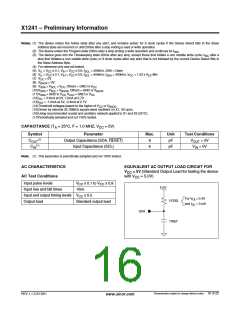
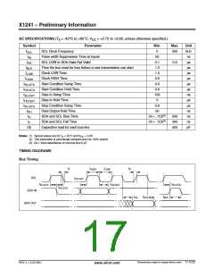
TIMING DIAGRAMS
Bus Timing
t
t
t
t
R
F
HIGH
LOW
SCL
SDA IN
t
SU:DAT
t
t
t
SU:STO
SU:STA
HD:DAT
t
HD:STA
t
t
t
BUF
AA
DH
SDA OUT
Characteristics subject to change without notice. 17 of 22
REV 1.1.3 2/13/01
www.xicor.com

 XICOR [ XICOR INC. ]